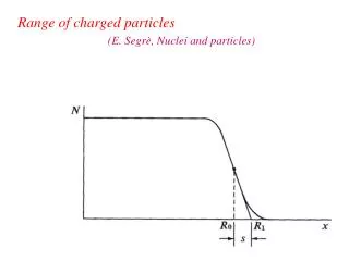
Download
1 / 12
150 likes | 486 Vues
The Use of Multiwire Proportional Counters to Select and Localize Charged Particles. Contents 1. What is MWPC ? 2. Method of detection 3. Measurement of the properties of MWPC 4. Summary. Nucl . Instrum . & Methods 62 (1968) 262

E N D
The Use of Multiwire Proportional Counters to Select and Localize Charged Particles Contents 1. What is MWPC ? 2. Method of detection 3. Measurement of the properties of MWPC 4. Summary Nucl. Instrum. & Methods 62 (1968) 262 G. Charpak, R. Bouclier, T. Bressani, J. Favier and C. Zupancic Shibata Lab. 07-03380 Masachika Iwai
1. What is MWPC(MultiWire Proportional Counters)? MWPC is a detector of the incident positionof charged particles, which is developed by CharpakIn 1968. 15 mm MWPC collision MWPC is made of a plane of independent wires in parallel and in same interval placed between two plane electrodes, the anode wires of MWPC act as independent proportional counters. particle beam detect → after development, MWPC is exploited in many experiments of elementary particles and an atomic nucleus → in 1992 Charpak received a Nobel Prise in physics
2. Method of detection A flow chart of detection Equipotentials in a chamber particle 7500 μm (7.5 mm) cathode electron X-ray drift region 30 μm avalanche region 20 μm pulse Anode wire anode 1. Formation of primary ionization electrons. cathode 2. The electrons driftalong the electric field lines. 3. Avalanche take place near the anode wire. 4. Output from an anode wire. particle
- Selecting of applied voltage - By setting applied voltage up from 1400 V to 1650 V, each wire works as an independent proportional counter. → The region of operation of MWPC is the proportional region. < features of the proportional region > ・ partial discharge ・ high amplification → output from only the nearest wire from the incident position of particles
- Selecting of gas - Ex 1. argon + pentane Ex 2. argon + heptane ・ reason of selection of argon - low value of W → increase of the numbers of primary electrons high pulse height - low threshold for proportional amplification → high amplification ・ reason of selection of pentane and heptane • absorption of ultraviolet quanta • → preventing of propagation output from single wire → acquisition of gas amplification factor of Pulse height 100 mV
3. Measurement of the properties of MWPC < pulse height as a function of distance from the wire > Experiment content anode MWPC 2 mm Beam of 370 MeV/c Collimated to 0.6 mm ・A beam of protons incidents on MWPC as they vary the distance from the wire. • Distance : on the wire, 0.5 mm, 0.75 mm, 1 mm and 1.5 mm - Measurement : pulse height
Result on the wire Wire space 2 mm 0.5 mm Pulse height as a function of Distance from the wire 0.75 mm counts 1 mm 1.5 mm On the wire ~ 0.75 mm : a lot of high pulse height → signal of incident particles 1 mm ~ 1.5 mm : a lot of low pulse height → signal of noise Pulse height Thanks to high amplification in proportional region, MWPC can distinguish between signal of particles and signal of noise.
<efficiency > Discrimination level on the wire Wire space 2 mm 0.5 mm 0.75 mm counts 1 mm 1.5 mm Efficiency of detection as a function of position Pulse height as a function of Distance from the wire To get the high efficiency near the wire, low discrimination level was set up. Pulse height → Incident particles up to 0.75 mm from the wire can be detected with an efficiency close to 100 %.
< localization > Thanks to operate in proportional region, output from single wire can be gotten. → maximum error is 1 mm. ( wire space : 2 mm ) Error = | value of measurement - the position of incident particles | 2 mm The region of incident particles →Localization of the position between the wire is possible, making use of the arrival time of the pulse (time delay). Value of measurement
Time delay - idea to Drift Chamber - content A beam of protons incidents on MWPC as they vary the distance from the wire. - Distance : on the wire and 1 mm counts -measurement : time interval between the traversal of MWPC by the electron and the detection on the wire result Time Time distribution is shifted on the right side as incident position of particles go away from the wire. 30 ns On the wire Drift velocity 1 cm ~ 300 ns Reason : the difference of drift-distance → time delay 1 mm counts To better spatial resolutions, making use of time delay → to Drift Chamber Delay in the pulse as a function of the Distance wire - particle Time
4. summary • Each wire of MWPC acts as an independent proportional counter. • With argon-pentane and argon-heptane mixtures, high amplification is possible. • Incident particles up to 0.75 mm from the wire can be detected with an efficiency close to 100 %. • The maximum error of localization of the position of incident particles is 1 mm. • Time delay may be exploited to get better spatial resolutions.