Download
1 / 25
260 likes | 420 Vues
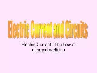
Electric Current and Circuits. Electric Current: The flow of charged particles. Electric Current. Electric current flows from higher potential difference (voltage) to lower potential difference, which is related to the position of the charges.

E N D
Electric Current and Circuits Electric Current: The flow of charged particles
Electric Current • Electric current flows from higher potential difference (voltage) to lower potential difference, which is related to the position of the charges. • Charges that move around a closed loop is called an electric circuit.
Electric Circuits • At the very least, circuits include a conductor (wire), a power source (battery), and the electric current passing through the conductor. • Current flows from the positive to the negative terminal.
Power • Measures the rate at which energy is transferred • P = Power, measured in Watts (W) • I = Current, measured in Amperes (A) • V = voltage difference, provided by power source, measured in volts. P = IV
Electrical Energy • Rate of power used over time • E = energy, measured in Joules • P = power, measured in Watts • T = time, measured in seconds E = Pt
Sample Problem • A 6V battery delivers a 0.5 A current to an electric motor that is connected across its terminals. How much power is consumed by the motor? If the motor runs for 5 minutes, how much electrical energy is delivered?
Resistance and Ohms • Resistance determines how much current will flow. • Resistance can be determined by the type of conductor present – what type of material is being used to conduct electricity? • Resistance can also be affected by the size of your wire.. • Resistors can also be placed in the circuit to control voltage/current running through the circuit.
Resistance and Ohms • Resistors are devices designed to have a specific resistance. They may be made of long thin wires, graphite, or semiconductors.
Ohm’s Law • R = Resistance, measured in Ohms (Ω) • V = Voltage difference – measured in Volts • I = current – measured in Amps R = V/I
Sample Problem • A 30 V battery is connected to a 10 Ωresistor. What is the current in the circuit?
Drawing Diagrams • Simple circuits can be described in words and translated into drawings of the parts. • A diagram of an electric circuit is drawn using standard symbols for the circuit elements. Diagrams are called schematics.
Sample Problem • Draw a circuit diagram to include a 60 V battery, an ammeter, and a resistance of 12.5 Ω in a series. Be sure to include the value of the ammeter
Series Circuits • A connection of electrical devices in a circuit where there is only one path.
Series Circuits • If there is more than one voltage source: V source = VA + VB • If there is more than one resistance, use the equivalent resistance for series circuits formula: R = RA + RB + …. • Calculating Current: I = V/R
Voltage Dividers • Used to produce a voltage source of desired magnitude from a higher voltage battery. • Suppose you have a 9 V battery but only needs 5V – you would use a votage divider • VB = VsourceRB / RA +RB OR V = IRB • VB is your new, dropped voltage, RB is the resistance across VB
Solving with Voltage Dividers • A 9 V battery and two resistors 400Ω and 500Ω are connected as a voltage divider. What is the voltage across the 500Ω resistor? Step 1 – Draw your schematic diagram. Step 2 – Solve for Current (be sure to add R together) Step 3 – Use VB = VsourceRB / RA +RB
Parallel Circuits • A circuit in which there are several current paths. • Equivalent resistance for Resistors in Parallel. 1/R = 1/RA + 1/RB + 1/RC + …
Sample Problems • Three resistors, 60Ω, 30Ω, and 20Ω, are connected in parallel across a 90 V battery. • Find the current through each branch of the circuit. • Find the total resistance (use equivalent resistance formula) • Find the current through the battery. (hint: use the resistance found from above)
This is a multimeter; it measures current, voltage and resistance.
Set up your circuit to include multimeterusing alligator clips