Download
1 / 37
380 likes | 525 Vues
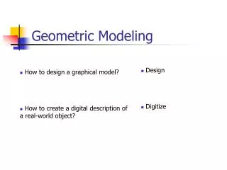
This guide covers essential tasks in geometric modeling of ship hulls using Rhino3D. It is tailored for lab classes in marine engineering and naval architecture. The content includes generating hull offsets, modeling specific areas like the deck and camber lines, and extracting main lines from surfaces. Detailed procedures for transitioning from curves to surfaces and vice versa are outlined. Additionally, methods for creating drawings from models and exporting data in CAD formats are discussed, providing a comprehensive learning resource for students in the field.

E N D
Geometric Modeling of the Hull Guide for Lab Classes Prof. Manuel Ventura / José Varela www.mar.ist.utl.pt/mventura Ship Design I MSc in Marine Engineering and Naval Architecture
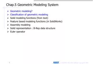
Contents • Task 1. From Curves to Surfaces • Task 2. Modeling Specific Areas • Task 3. From Surfaces to Curves • Task 4. From Main Curves to Surfaces • Class 5. From the Model to the Drawing • Class 6. Creation of a Bow Thruster Tunnel Hull Modelling Lab Classes
Task 1. From Curves to Surfaces (1) • Generate the hull offsets from the Series 60, using HullS60, and for example the following main dimensions: Lpp = 130.0 B = 22.0 T = 8.2 DisplV = 0 Cb = 0.78 • Import the resulting cross sections and contours AV/AR in DXF format into Rhino3D • Create layers: Curves, Surfs, BaseLine, FOB, FOS, DeckEdge, Planes • Set layer <Curves> active and fit curves to the imported polylines • Move into the <Front> view, hide the <DXFImport> layer, and <Trim> the first and last sections by the respective stern and bow contours • Set layer <BaseLine> active and draw a single line between the first points of the stern and of the bow contours Hull Modelling Lab Classes
Task 1. From Curves to Surfaces (2) Hull Modelling Lab Classes
Task 1. From Curves to Surfaces (3) • Set layer <FOB> active and draw a curve joining the points of each section that lie on the base plane • Set layer <Surfs> active and generate the bottom surface by <Edge Curves> using the base line curve and the FOB as edges • Generate a single hull surface by <loft> curves from the stern contour to the bow contour • Determine the FOS curve • Intersect the surface with the tangent plane • To guarantee a complete intersection curve move the plane inwards by a small distance (Example: 0.05 m) • Fair the resulting curve • Project the curve back into the correctly positioned tangent plane • Set layer <DeckEdge> active and draw a curve joining the upper of each cross section and contour Hull Modelling Lab Classes
Task 1. From Curves to Surfaces (4) Hull Modelling Lab Classes
Task 1. From Curves to Surfaces (5) Hull Modelling Lab Classes
Task 1. From Curves to Surfaces (6) • Curve can be faired interactively by deleting and moving points • <Transform/Smooth> function can also be used, but is not very efficient Hull Modelling Lab Classes
Task 1. From Curves to Surfaces (6) Surface/Plane/3 Points Curve/Curve From Objects/ Project Curve/Free-form/ Interpolate Points Hull Modelling Lab Classes
Task 1. From Curves to Surfaces (7) View / Set CPlane / To Object Curve/Extend Curve/ Extend Curve Hull Modelling Lab Classes
Task 1. From Curves to Surfaces (8) Hull Modelling Lab Classes
Task 2. Modeling Specific Areas • Deck surface • Sheer line • Camber line • Planar/curved surfaces • Determine the deck line at side (DAS) • Bulb surface • Cross section in the FWD PP • Bow contour • Waterline at bulb height • Bow tip • Stern panel Hull Modelling Lab Classes
Task 3. From Surfaces to Curves • Extract the main lines from an existing surface model • Center plane longitudinal contour • FOB • FOS • Midship section • Additional sections FWD/AFT and at the FWD PP • LWL • DAS • Lines fairing Hull Modelling Lab Classes
Task 4. From Main Curves to Surfaces • Generation of the hull surface from the main lines • Introduce knuckle lines by projection of curves into the surfaces • Split and rebuild surfaces affected by knuckles Hull Modelling Lab Classes
Main Lines for Hull Modeling Hull Modelling Lab Classes
Processing the Curves Control points before refit curves If necessary, create auxiliary curves to define the four boundaries Split curves in order to define four boundaries for each surface Control points after refit curves Hull Modelling Lab Classes
Generating the Surfaces (1) Use the four boundaries to build each surface (<surface by curve network> in Rhinoceros 3D) Generate auxiliary surfaces to control known tangents at the boundaries Use the previous surface to define the boundary continuity of the next adjacent one Hull Modelling Lab Classes
Generating the Surfaces (2) Use planar surfaces whenever possible. Simplify… Simplify… Simplify! Sweep the bulb section trough two rails to create the surface Hull Modelling Lab Classes
Generating the Surfaces (3) After some hours of hard work… Hull Modelling Lab Classes
Class 5. From the Model to the Drawing • Extract from the surface model of the half-hull the curves for the traditional Lines Plan drawing: • Cross sections • Longitudinal sections • Waterlines • Diagonals • Export for other CAD systems • DXF format • IGES format Hull Modelling Lab Classes
Getting the Lines Plan - Sections Define the location of each section. Make sure you create one at the after and another at the forward perpendiculars Project the lines into the hull surfaces. Note that the projection direction must be perpendicular to the profile view plane. Hull Modelling Lab Classes
Getting the Lines Plan - Waterlines Define the location of each waterline. Make sure you create one at the design draft Project the lines into the hull surfaces. Note that the projection direction must be perpendicular to the profile view plane. Hull Modelling Lab Classes
Getting the Lines Plan - Buttocks Define the location of each buttock. Project the lines into the hull surfaces. Note that the projection direction must be perpendicular to the top view plane. Hull Modelling Lab Classes
Drawings in AutoCad Export lines to AutoCAD (.dxf, .dwg) Hull Modelling Lab Classes
Creating the Drawing in AutoCad (1) Select layout view Selected window Create the three views to the model in the layout using mview command Change to model space in layout view and select each window Hull Modelling Lab Classes
Creating the Drawing in AutoCad (2) Set the appropriate view for each selected window Set the same scale for each window: Zoom->Scale->1/200xp Change back to paper space view Hull Modelling Lab Classes
Aligning the Views in AutoCad (1) Select the view you want to align Hull Modelling Lab Classes
Aligning the Views in AutoCad (2) Move the view window to the correct position: . Select move . The origin point is a point on the deck in the section view . The destination point must be aligned with a point on the deck in the profile view . Use OTrack option to align destination point with the point on the deck Hull Modelling Lab Classes
Aligning the Views in AutoCad (3) Do the same procedure for the waterline view. Now the lines in the views are aligned and the view windows are not. Although is not necessary you can align the views by aligning their corner points in the paper space. This will have no effect on the position of lithe lines. Hull Modelling Lab Classes
Aligning the Views in AutoCad (4) Create a new layer called “MViews”, select the three views and change them to that layer. Then hide the layer “MViews” and the borders of the windows will be hided. Then, don’t forget to complete the lines plan… Hull Modelling Lab Classes
Bow Thruster Tunnel • Create a tunnel for the bow thruster at • Diameter = 1.20 m • Height = 2.5 m • Distance to FPP = 2.0 m • The tunnel shall have an asymmetrical conic section before the intersection with the side shell • The edge at the side shell shall be filleted with a radius of 0.01 m Hull Modelling Lab Classes