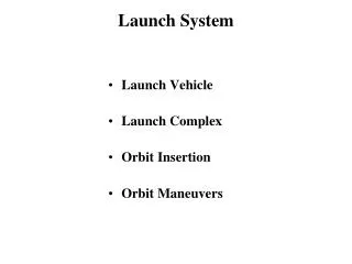
Launch System
Launch System. Launch Vehicle Launch Complex Orbit Insertion Orbit Maneuvers. German V-2 Fins for stability and steering Exterior skin with Propellant tanks within Single stage. U.S. Launch Vehicles Engine gimbals Wall of tank and skin of vehicle one and the same Multiple Stages.

Launch System
E N D
Presentation Transcript
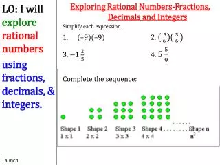
Launch System • Launch Vehicle • Launch Complex • Orbit Insertion • Orbit Maneuvers
German V-2 Fins for stability and steering Exterior skin with Propellant tanks within Single stage U.S. Launch Vehicles Engine gimbals Wall of tank and skin of vehicle one and the same Multiple Stages Booster Design
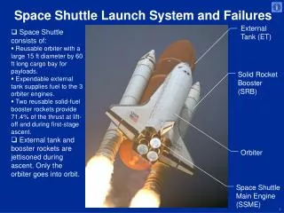
Launch Vehicles • Expendable • Air Force and commercial US systems • Divided into small, medium, and heavy classes • Next generation of expendable vehicles in development • Manned • Space Shuttle • Reusable • Test vehicles only
Launch Ranges Launch ranges provide tracking, telemetry, communications, command & control, and other support necessary for safe and successful space lift operations, and aeronautical and ballistic missile tests.
Launch Fundamentals Launch Events Step 7: Mechanical deployments Shroud Protects the spacecraft Step 6: Satellite initial checkout Upper stage Orbit insertion rocket engines and propellant tanks Step 5: Orbit insertion Step 4: Shroud opening Step 3: Main engine cut-off and separation Main vehicle Primary liquid or solid rocket propellant tanks Booster packs Solid strap-ons for some rockets to increase initial thrust Step 2: Booster cut-off and separation Step 1: Ignition and launch Engine / nozzles Mechanism for combining propellants and focusing thrust
V Step 1 Launch into parking orbit (With orbit insertion burn) North Pole V2 Minimum energy transfer Burn 1 to change path Burn 2 to change to higher orbit Step 2 N V1 Orbit plane transfer (With vector thrust burn) Step 3 V Usual Launch Sequence
Launch Ranges • Ranges usually located to minimize overflight of populated areas and reduce • potential debris hazards • Launch site latitude limits the inclination of the satellite’s orbit • The minimum inclination of the orbit is equal to the latitude of the launch site • To get to a lower inclination, satellites need to go through an orbit plane transfer
DOD LAUNCH LOCATIONS • CAPE CANAVERAL AFS / KENNEDY SPACE CENTER • (EASTERN SPACE LAUNCH RANGE) • SHUTTLE • TITAN IV • TITAN II • ALTAS • DELTA • VANDENBURG AFB • (WESTERN SPACE LAUNCH RANGE) • TITAN IV • TITAN II • ALTAS • DELTA 37 DEG SPACE LAUNCH AZIMUTH 30 DEGREES LATITUDE 112 DEG 201 DEG SPACE LAUNCH AZIMUTH 158 DEG
Launch Window • The “launch window” is the period of time during which the launch must occur to achieve a desired orbit • Duration of window is determined by desired orbit, launch location, weather, and launch vehicle performance • Examples of issues: • Vehicle may require specific orbit for rendezvous • Vehicle may require orientation to get correct solar array exposure before reaching final orbit
Launch FundamentalsScience force = (mass) x (acceleration) f = (m)(a) The thrust of a launch vehicle must oppose gravity and atmospheric drag To get into orbit, a vehicle must achieve a velocity of mach 24 (24 times the speed of sound) FORCE FORCE & TIME FORCE & TIME & FUEL Thrust = Pounds or Kg Impulse = Pounds per sec Specific Impulse (Isp) = Newtons per sec Isp = Thrust (lb) fuel weight (lb) burned in 1 sec
Mass Ratio of a Vehicle MR = mf /m0 Mass Ratio (MR) is the ratio between the booster mass before the rocket engine burn (mf ) divided by the booster mass after rocket engine burn (m0 ).
V V V2 V2 V1 V1 PROPULSION: GETTING INTO AND AROUND IN ORBIT NORTH POLE ORBIT PLANE TRANSFER (WITH VECTOR THRUST BURN) LAUNCH INTO PARKING ORBIT (WITH ORBIT INSERTION BURN) NORTH POLE NORTH POLE HOHMANN (MINIMUM ENERGY) TRANSFER (BURN 1 TO CHANGE TO ELLIPTICAL ORBIT AND BURN 2 TO CHANGE TO HIGHER ALTITUDE CIRCULAR ORBIT) FAST TRANSFER (BURN 1 TO CHANGE TO LARGE ELLIPSE AND BURN 2 TO FORCE INTO NEW ORBIT)
Launch from Vandenberg • Launch site latitude 37 deg N latitude • Desired Orbits • Inclination 80 degrees 104 degrees • Apogee 250 NM 250 NM • Perigee 100 NM 100 NM • What is the launch azimuth for each orbit? • What velocity (V) must the payload have in each desired orbit at perigee and apogee?
Launch Azimuth * cos Inclination = cos Latitude x sin Azimuth sin Azimuth = cos Inclination/cos Latitude Posigrade Orbit, i.e., with Earth’s rotation sin Az = cos 80/cos 37 = sin 12.56 degrees Launch Azimuth = 167.44 degrees Retrograde Orbit, i.e., against Earth’s rotation sin Az = cos 104/cos 37 = sin -17.63 degrees Launch Azimuth = 197.63 degrees North 167 198 * Formula from page 81 Space Handbook, Analysts Guide.