Preliminary Design Review of Air Launch System for ISS Payload Delivery
The Air Launch System Preliminary Design Review, conducted on April 7, 2008, presents a multi-stage vehicle concept that utilizes a high-altitude carrier aircraft to launch small payloads to the International Space Station (ISS). The project aims to minimize launch costs and enhance reliability through innovative design and engineering practices, including SolidWorks modeling, aerodynamic analysis, and thermal assessments. A comprehensive trade study evaluates various carrier aircraft, with the C-17 selected for its capacity and availability. The presentation details design requirements, performance metrics, and future tasks.

Preliminary Design Review of Air Launch System for ISS Payload Delivery
E N D
Presentation Transcript
Air Launch System Preliminary Design Review April 7, 2008 Dan Poniatowski (Team Lead) Matt Campbell Dan Cipera Pierre Dumas Boris Kaganovich Jason LaDoucer Isaac Landecker Brandon Miller Long Nguyen Rizwan Qureshi Angela Reesman Cory Sorenson 1
Project Overview • Goals and Motivation • Design a multi-stage vehicle that is launched from high altitude and is capable of delivering a small payload to the ISS. • The vehicle must be readily available, simple to use and require a minimum amount of preparation prior to launch. • The motivation is to reduce the cost and improve reliability of launching a small payload into orbit by using an aircraft as the first lifting stage instead of a rocket. • Scope and Deliverables • Produce a Solid Works model of each system component. This includes the aircraft launch system, booster assembly and satellite. • Use a variety of techniques including theory, Solid Works, Joe Mueller’s orbital mechanics code and Professor Hammer’s thermal analysis code to ensure the system can accomplish its mission.
Project Overview – Major Tasks Trade Studies - Provide specifications, pros and cons of many options. This includes carrier aircraft, boosters and satellite components. Percent Complete: 100% • Aircraft Analysis Tasks • Select a carrier aircraft • Design delivery and release mechanism for the booster • Produce SolidWorks models of all components. Percent Complete: 95%
Project Overview – Major Tasks • Booster Design Tasks • Select the rocket motors used by the booster • Run gravity turn simulations usign Joe Mueller’s code • Produce a SolidWorks model of the booster assembly. Percent Complete: 90% • Satellite Design Tasks • Find Delta-v required for station keeping • Estimation of disturbance forces • SolidWorks models of the satellite assembly • Determine hardware components • Performing thermal analysis • Determining power requirements Percent Complete: 60%
Aircraft Team Spring Semester April 7, 2008 Presenter Names: Matt Campbell, Isaac Landecker, Dan Cipera, Brandon Miller
Overview • Requirements • Aircraft Analysis Trade Study • AIAA Trade Study • Delivery Method • Direction • “The Exit” • Drop Dynamics • Parachutes • Requirements Completed Sarigul-Klijn 1
Requirements • Identify several potential carrier aircraft and determine the key performance metrics: • Aircraft Compatibility • Maximum takeoff weight • Derive maximum dimensions and mass of launch vehicle • Derive the maximum flight path angle as a function of launch vehicle mass, altitude, velocity
Requirements • Perform structural analysis for attachments • Compare with loads associated with missiles / bombs for which the aircraft is already designed to carry • Design attachment structure and release mechanism Old Designs
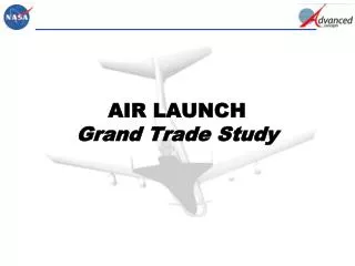
The Plan • Compare and contrast different possibilities for launch aircraft • Three Categories: Commercial, American Military, and Foreign Military • Determine which aircraft could meet the project requirements, and of those, select the one with best balance between performance, availability, and cost.
Aircraft Considered • Commercial: Boeing 777, Boeing 747-400, Airbus A330, Lockheed L-1011 • US Military: F-15, F-16 F-22, B-1B, B-2, B-52, C-5, C-17 • Foreign Military • European: Eurofighter, Rafale, Tornado • Russian: MiG-29, Su-27, Tu-22M, Tu-95, An-124
Parameters Considered • Performance: MTOW, Service Ceiling, Range, Payload capabilities • Availability: production status, numbers produced, locations available • Cost: cost of production for a new airframe
Best Methods of the Trade Study • Launch Direction: Forward Facing Launch • Increased payload by 30% compared with ground launch • Orientation: Stabilizing Parachute • Lightweight and reliable system • Extraction: Gravity Air Launch • Simple and reliable • Loads up to 60,000 lbs. have been demonstrated • 5 to 7 degree angle of attack • Carriage: Wheels and Pneumatic Tires • Low cost and reliable • No point loads on launch vehicle
The Choice • C-17 • Payload Capability =76,657 kg • Availability > 134 aircraft world wide • Cost ($/hr) = ~ $6,000 • In-air-refueling • Cargo Area
Delivery Method • Structure • Able to withstand 1.5 G’s of force on structure • Maintains a Safety Factors of 1.5 • Designed to withstand 30,000 N w/ 1.5 S.F. • Ramp • Total Weight • ~9,000 kg • Entire Wheel System weighs 36 kg a piece
Delivery Method • Wheels (R=0.4 m, t=0.22 m, P=135 kPa) • allow for constant pressure along rocket • Wheels are large enough to withstand pressure • No point loads • Large enough to dampen wheel frequency • Single flat tire will not cause any problems
Wheel Assembly Displacement Nodal Stress
Air Launch LLC Drop Footage (Source: www.airlaunchllc.com) The Drop
Drop Dynamics • Assumptions • Dimensions • Cargo Bay • Ramp • Rocket • Determine parachute required
Drop Dynamics • Drogue Parachute • 4ft diameter • Cd = 1.0 • Stabilizing Parachute • Mounted on top of rocket
Requirements Completed • Identify several potential carrier aircraft and determine the key performance metrics: • Vertical clearance inside aircraft • Maximum takeoff weight • Derive maximum dimensions and mass of launch vehicle • Derive the maximum flight path angle as a function of launch vehicle mass, altitude, velocity • Perform structural analysis for attachments • Compare with loads associated with missiles / bombs for which the aircraft is already designed to carry • Design attachment structure and release mechanism
Sources Sarigul-Klijn, Marti. Sarigul-Klijn, Nesrin. Hudson, Gary. Mckinney, Bevin. Menzel, Lyle. Grabow, Eric, “Trade Studies for Air Launching a Small Launch Vehicle from a Cargo Aircraft.” AIAA 21 June 2005: 1-12.
Booster Team Spring Semester April 7, 2008 Presenter Names: Boris Kaganovich, Angela Reesman, Pierre Dumas, Rizwan Qureshi 27
Design Goals Multi-stage booster for air launch application Minimum number of staging events to maximize overall system reliability Solid lower stage(s) for system launch readiness Liquid or hybrid upper stage for engine restart and more accurate orbit insertion Green propellants to simplify booster handling Fast launch readiness requires all propellants to be storable or made on-site Minimum vehicle mass to allow for wide range of carrier aircraft Minimize g-forces to allow for reduced payload mass and better payload survivability 28
Booster Design Process Prepared drag free model using Excel to simplify hand calculations of booster Delta V capability. Performed trade studies for commercially available: Hybrid rocket motors Solid rocket motors Liquid rocket motors for upper stage application 29
Upper Stage Motors Results of liquid motor trade study led to: SpaceX Kestrel 2 upper stage rocket motor Pressure-fed LOX-RP1 rocket motor 52kg motor and nozzle Isp of 330s Flight-proven design Currently in serial production 30
Booster Design • 3 stage booster • 1st stage: ATK Orion 50XL solid motor • 2nd stage: ATK Star 31 solid motor • 3rd stage: SpaceX Kestrel 2 LOX-RP1 pressure-fed liquid motor • Based on drag free model in the spreadsheet : • 25kg payload • 345 kg 3rd stage propellant • 8.63 km/s total Delta V • 6298 kg takeoff mass 31
Gravity Turn Simulations Launch Flight Path Angle: 87.97 deg. • Used Joe Mueller’s Matlab code to simulate gravity turn • Parameters that can be varied in code: • Flight Path Angle (FPA) • Height at which ignition 3 starts • Mass of Stage 3 Propellant
Launch trajectory • Simulations produced the following direct launch trajectory to reach ISS: 33
3D Orbit Matlab simulation produced the following orbit: 34
Further orbit simulations Satellite Tool Kit (STK) initial orbit simulations: 35
Satellite Team Spring Semester April 7, 2008 Presenter Names: Long Nguyen, Cory Sorenson, Jason LaDoucer 36
Major Requirements – Upper Stage Satellite • To deliver a one cubic foot, 2.2 lb package to ISS • Compute the delta-v required for station-keep with the ISS • Compute the minimum fuel required for station-keep • Perform initial sizing of upper stage satellite • Develop a basic CAD model of upper stage satellite
Motivation for satellite design • Reduce total mass required for launch • Lightweight • Low power consumption • Minimize volume • Minimize error
Trade Studies • Necessary Components • Processor board • Communication module • Attitude sensor & control • Inertial Measurement Unit • PRISMA (Swedish Satellite)
PRISMA Trade Study • Small experimental Swedish satellite • Designed for close range maneuvers • 140kg • 8 months • Has similar design features • Capable of performing necessary maneuvers
Final Components • LEON3 Processor board on a chip by • Volts Required – 3.3 V • Weight – 50 g • SSTL S-band module • Volt Required – 28 V • Weight – 1000 g Picture Source: http://www.sstl.co.uk /documents/S-Band%20Receiver.pdf
Final Components (Cont.) • MIMU by Honeywell • Volts Required – 28 V • Weight 4700 g • Bias 0.005 deg/hr • MiDES (Mini Dual Earth Sensor) by Servo • Volts Required – 28 V • Weight – 1500 g • Accuracy – 0.04 deg Picture source:http://www.servo.com /Mides%20LEO%20Brochure1.pdf
Micro thruster • Volt Required – 5 V • Weight – 70 g • Thrust capability of 0.5 to 2.3 N • Thrust variable • Approximately 6 thrusters Picture source: http://www.marotta.com/pdf/cold-gas-micro-thruster-article.pdf
Satellite Maneuvers • Changing orbit to match ISS • Delta V ~5.5m/s • Chase Maneuver • Large delta V • Phasing with ISS • Main Drivers • Fuel • Time
Satellite Environment • Did trade study to determine thermal/radiation environment and space debris • Using 90 minute orbital period, satellite exposed to sunlight side (395K) more so than dark side (173K) • Satellite in LEO within inner Van Allen radiation belt • Protection from space debris, UV radiation • Aluminized Mylar • Passive Thermal Control
Required Δv for station keep • Determined area of ISS (768 + 192 m2) • Ran simulations with Joe Mueller’s MATLAB code using three shapes (square, sphere, bullet) • Determined sensitivity of parameters (navigation, thruster Isp, areas) • Navigation errors (accuracy of position sensors) contribute the most to Δv • With single thruster, Δv required for mission (30 days) < 15.2 m/s or 2.2% of satellite mass
Things to finish • Determine mass of satellite with thermal protection • Run simulations to determine fuel requirements with known mass thruster selection and how many thrusters • Run simulations to determine stress and strain for known mass