Download
1 / 57
610 likes | 812 Vues
Environmental Geodesy. Lecture 6 (February 22/ March 1, 2011 ): Observing Earth's surface displacements: The Point-Techniques - Overview - VLBI - SLR - GPS/GNSS - DORIS - Augmentation Systems - Reflectometry. Overview.

E N D
Environmental Geodesy Lecture 6 (February 22/March 1, 2011): Observing Earth's surface displacements: The Point-Techniques - Overview - VLBI - SLR - GPS/GNSS - DORIS - Augmentation Systems - Reflectometry
Overview Changes in the Earth's shape are measured with a mix of ground- and space-based techniques. Two broad classes of techniques: - space-geodetic tracking techniques: - monitor the deformation of a polyhedron (points) defined by ground-based networks of tracking stations; - use either passively signals from satellites (GNSS) or stellar objects (VBLI) or actively send out signals to satellites (SLR and DORIS); - air- or space-born remote sensing techniques: - send signals from airplanes or satellites to the Earth's surface and utilize the reflections to map the surface. Space-geodetic tracking methods provide time series of point movements: - high temporal resolution; - high accuracy; - tracking stations normally placed on the land surface. Remote-sensing techniques in general: - have much lower temporal resolution; - provide information with potentially high spatial resolution and much better coverage, including the surface of oceans, lakes, and ice sheets.
Overview http://itrf.ign.fr/GIS/
Overview The geometric space-geodetic techniques in general: - consist of a ground-based component of fixed stations; - have the ability to track the motion of satellites or astronomical objects (moon, quasars) with electromagnetic waves (including visible light). These stations can be: - passive in the sense that they do not emit signals but only receive signals from remote sources (GNSS, VLBI); or - active, i.e., emit signals (SLR, LLR, DORIS). Common to all these methods is: - data analysis requires a good a priori station motion model describing in particular any variation with periods shorter than the analysis interval (for example, 1 day). - For the methods based on range measurements, effects on the satellite also need to be accommodated. Coordinate time series resulting from space-geodetic analyses therefore are generally residuals with respect to the station motion model and other modeled effects.
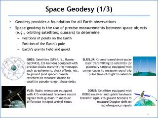
VLBI VLBI; Very Long Baseline Interferometry is a space-geodetic technique: - based on radio astronomy; - developed in the 1970s. A radio interferometer consists of a pair of directional antennas (radio telescopes) receiving radio signals from sources in a targeted radio frequency band. The signals from the two receivers are cross-correlated (multiplied and accumulated) to produce a cross-correlation "fringe pattern''. VLBI - uses networks of radio antennas typically 20-30 meters in diameter; - observe radio signals from extragalactic objects (quasars). Quasars are at such great distances from Earth that they provide fixed points in the sky. Their transverse physical motion cannot be detected with any existing observing system.
VLBI A radio signal from a quasar passing a VLBI station is received and recorded digitally with very precise time provided by a hydrogen maser. The same signal will travel an additional distance c·τbefore arriving at the second VLBI station, where c is the speed of light and τ is the time difference of the signal arriving at the first and second station. The distance τ depends on the length of the baseline between the stations and its orientation with respect to the direction to the quasar. The time delay between the arrival times at the two stations can be determined with a precision equivalent to a few millimeters using purpose-built hardware correlators.
VLBI http://ivscc.gsfc.nasa.gov/about/index.html
SLR/LLR Satellite laser ranging (SLR) and lunar laser ranging (LLR) use very short laser pulses and fast electronics to measure the instantaneous round trip time of flight of the pulses to satellites equipped with special retroreflectors and to retroreflectors on the Moon, respectively. This provides range measurements of a few millimeter precision which are accumulated to help define the terrestrial reference frame and to support active spaceborne Earth sensing missions and studies of lunar science and fundamental physics. The fundamental targets for the reference frame are LAGEOS-1 and -2, whose spherical shape and high mass-to-area ratios provide long-term orbital stability for measuring the dynamics of the Earth. The basic range measurement is sensitive to any geophysical process that changes the distance between the satellite and the observing station, such as - displacements of the satellite due to perturbations of the Earth's gravitational field, - motions of the observing station due to tidal displacements or plate tectonics, or - a change in the orientation of the Earth (which changes the location of the observing station with respect to the satellite). These and other geophysical processes must be modeled when fitting the satellite's orbit to the range measurements as obtained at a number of globally distributed tracking stations. Adjustments to the a priori models used for these effects can then be obtained during the orbit determination procedure, thereby enabling, for example, the determination of station positions and Earth orientation parameters.
SLR/LLR Principle of Satellite and Lunar Laser Ranging
SLR/LLR Laser Ranging Satellites LAGEOS-1, -2
SLR/LLR The International Laser Ranging Service (ILRS) network - consists of about 40 SLR and two LLR stations - currently tracks on a daily basis about 30 satellites ranging in altitude from 400 km to 22,000 km and four retroreflectors on the Moon. The ILRS: - coordinates laser ranging activities, - develops standards and specifications necessary for product consistency, - sets priorities and tracking strategies, - oversees data operations, and - provides quality control and a user interface.
SLR/LLR Laser ranging activities support programs primarily in geodetic, geophysical, and lunar research activities. The ILRS currently provides the IERS with weekly solutions for station coordinates and EOPs for the monitoring of the ITRF, contributing exclusively the definition and time-varying motion of its origin (with respect to the CM), and in combination with VLBI, its scale. Other contributions include the - estimation of static and time-varying components (harmonic coefficients) of Earth's gravity field; - accurate satellite ephemerides for validation of altimetry (for satellites such as ICESat), - relativistic and satellite dynamics tests; and - Lunar ephemeris for relativity studies and lunar libration for lunar interior studies.
SLR/LLR SLR, as a backup system, has also provided supported missions whose primary tracking systems failed (e.g., GFO-1, ERS-1, Meteor-3M, etc.). Prior to the launch of CHAMP in the 2000, knowledge of the Earth's gravity field was almost uniquely based on SLR and terrestrial gravity measurements. SLR is an essential calibration technique for the GNSS technique and for the new space missions CHAMP, GRACE, and GOCE.
SLR/LLR SLR Network
SLR/LLR Lunar Laser Reflectors (Apollo 11, Apollo 14, Apollo 15)
SLR/LLR LLR is similar to that of SLR except that the laser retro-reflector is located on the Moon instead of on an artificial satellite. LLR is technically more challenging than SLR because of the need to detect the much weaker signal that is returned from the Moon. Larger, more powerful laser systems with more sophisticated signal detection systems need to be employed in LLR; Consequently, there are far fewer stations that range to the Moon than range to artificial satellites:
SLR/LLR Lunar Laser Reflectors (Apollo 11, Apollo 14, Apollo 15); some results: - The Moon is spiraling away from Earth at a rate of 38 mm per year. - The Moon probably has a liquid core of about 20% of the Moon's radius. - The universal force of gravity is very stable. The experiments have put an upper limit on the change in Newton's gravitational constant G of less than 1 part in 1011 since 1969. - The likelihood of any composition-dependent differential acceleration of the Moon and Earth towards the Sun has been ruled out to high precision, strongly supporting the validity of the Strong Equivalence Principle. - Einstein's theory of gravity (the general theory of relativity) predicts the Moon's orbit to within the accuracy of the laser ranging measurements.
SLR/LLR SLR Network
GNSS Global Navigation Satellite Systems (GNSS) are the successors of the so-called Doppler systems. They are based (1) on about 30 to 45 satellites emitting microwave signals on at least two carriers, and (2) an unlimited number of receivers capable of tracking the signals of all satellites simultaneously in view (usually between 4 and 12). GNSSs occupy the so-called MEO-belt. The satellites orbit the Earth in heights around 20000 km and complete one revolution within approximately half a day.
GNSS The U.S. GPS with nominally 24 satellites, uniformly distributed in six orbital planes, which are in turn inclined by 55 deg with respect to and separated by 60 deg in the equator, is the best known and most widely used GNSS. The Russian GLONASS with nominally 24 satellites in three orbital planes inclined by 63 degrees with respect to the equator and separated by 120 degrees in the equator, is currently not fully available (in January 2007 only nine satellites were fully operational). The first experimental satellite of the European GALILEO system (GIOVE-A) was launched on December 28, 2005 and early in May 2007, this satellite successfully transmitted its first navigation message, containing the information needed by user receivers to calculate their position. GALILEO is planned to reach FOC in 2012. By then, this GNSS is projected to have 30 satellites positioned in three circular MEO planes.
GNSS The microwave band (the L-band) of the electromagnetic spectrumallows for the weather-independent use of the systems, The two carriers allow for the elimination of the ionospheric refraction. The quasi-simultaneity of the observations of different GNSS satellites allows for the elimination (or significant mitigation) of the synchronization errors of the receiver clock with respect to GPS system time. The GNSS were/are deployed primarily for navigation -which is by definition a real time task.
GNSS The GNSS may, however, also be used for science and other positioning applications requiring high accuracy. In this case the observable of choice are not the signals (also called code) modulated on the carrier waves, but the reconstructed carrier itself. The analysis is usually done in the post-processing (but also increasingly in the real-time) mode. This carrier phase observable may be reconstructed with mm-accuracy, which in turns allows for mm-accurate relative positioning, provided not only the receiver clock corrections are estimated from the observations, but the satellite clock corrections, as well. Alternatively to the estimation of the clock errors one may also form the so-called double difference observation (the between-satellite-difference of two between-receiver-difference observations, all observations assumed to be simultaneous).
GNSS For science, the following quantities may be determined on a daily basis from a global network of well monumented, permanently operating tracking receivers (the ground tracking network): - GNSS geocentric satellite positions for the entire day (accurate to few cm) - GNSS satellite clock corrections (accurate to a few ten picoseconds) - Mean receiver coordinates per day (accurate to a few mm) - Position of the Earth's rotation axis on the Earth's surface (polar wobble) (daily estimates, accurate to few mm) - Length of day (daily estimates, accurate to a few microseconds) - Tropospheric zenith delays for all stations (which in turn allow it to estimate the total water vapor content over the station - provided station pressure and temperature are recorded as well) with high time resolution. - Global models/maps of mean electron content (two hours time resolution) - time and (in particular) frequency transfer between time laboratories (sub- nanosecond accuracy)
GNSS It is in essence this catalog of quantities, which is determined every day by the International GNSS Service (IGS) since January 1, 1994. Since 2003 not only the GPS, but also GLONASS observations are used routinely to derive the official IGS products. The IGS products are based on a weighted combination of the IGS Analysis Centers, generated by the IGS Analysis Coordinator (at least) on a daily basis. The series of IGS station coordinates is in turn used by the IERS to realize the ITRF together with the corresponding results of the other space-geodetic techniques VLBI, SLR/LLR, and DORIS. The large number of IGS sites (currently more than 400 provides easy access to the ITRF for the user community - going far beyond science.
GNSS The IGS series of Earth rotation parameters are also used by the IERS to issue the official transformation parameters between the ICRF and the ITRF. The full set of transformation parameters contains in addition to the above mentioned items UT1-UTC and the nutation angles. These latter quantities can only be provided accurately by VLBI. In summary one may state that the GNSSs are the workhorses of space geodesy. They provide the basis for numerous applications in geodesy and surveying (virtually all national first order networks refer to the ITRF and are realized using the IGS products) and in the wider area of Earth sciences (in particular atmosphere and ocean sciences, meteorology, and climatology).
GNSS IGS Network
GNSS Publicly available stations
GNSS GPS stations: a heterogeneous network ...
DORIS The Doppler Orbitography and Radiopositioning Integrated by Satellites (DORIS) system was designed and developed by the CNES, in partnership with the GRGS and the IGN, for precise orbit determination of altimeter missions, and consequently also for geodetic ground-station positioning. Like GNSS, DORIS is a satellite geodetic technique based on microwave signals, however DORIS is an uplink system from ground stations to spacecraft. DORIS beacons transmit on two frequencies, namely 2036.25 Mhz, and 401.25 Mhz. The DORIS system consists of: - a ground segment, the network of beacons, as well as - a space segment, the user satellites, a subset of which actually contribute to the determination of IERS products such as station positioning, and Earth orientation. One characteristic of the DORIS system that is unique with respect to the other space geodetic techniques is the much more homogeneous station distribution. It is the only space geodetic technique with a balanced station distribution in both the Northern and Southern Hemispheres. In addition, another important characteristic is the relative stability of the sites and their longevity with relatively few antenna changes over time.
DORIS The DORIS network consists of 50 to 60 stations around the world. The beacons assure an 80% coverage of user satellite orbits near 800 km altitude, and a 95% coverage of user satellite orbits at 1335 km altitude. Each ground beacon is equipped with - a dual frequency transmitter, - an ultra-stable oscillator (USO) delivering the reference frequency with a stability of 5.0·10-13 over 10 to 100 seconds, - an omni-directional dual-frequency antenna, - a battery pack providing backup power to the beacon during electricity outages, - a meteorological package providing in situ measurements used for the tropospheric correction. Functionally, each beacon may play ne of several roles: (1) broadcast upload transmission, (2) time and frequency reference station, (3) time correction beacon, and (4) positioning station. Late in 2005, three stations played the role of master beacons, whose clocks are tied to atomic clocks, and whose delays are estimated with respect to TAI atomic time by time/frequency experts. The master beacons serve as time and frequency references for the DORIS system, and handle uploading of data and commands needed by the DORIS spacecraft receivers.
DORIS Illustration of two DORIS stations: - Rothera, Antarctica (top), - Thule, Greenland (bottom).
DORIS As of 2006, there were co-locations between DORIS antennae and other active IERS techniques at 38 of the 56 permanent DORIS stations. These co-locations are distributed as follows: - with GPS at 37 sites, - with SLR at 9 sites, and with - VLBI at 7 sites. Among these stations, fifteen sites have three co-locations (8 for GPS+SLR+DORIS, and 7 for GPS+VLBI+DORIS). Only two sites worldwide have co-locations with four techniques (GPS+VLBI+SLR+DORIS): Hartebeesthoek and Greenbelt. Since the 1990's, with the growing interest in monitoring changes in global mean sea level, DORIS stations havebeen increasingly sited near tide gauges. As of 2006, 21 DORIS tide-gauge co-locations were available.
DORIS The space segment of the DORIS system consists of receivers on user satellites in low Earth orbit. Four satellites have carried first-generation DORIS receivers: TOPEX/Poseidon, SPOT-2, SPOT-3, and SPOT-4. A new second-generation dual channel DORIS receiver was developed in the 1990's. This receiver has been carried on ENVISAT, and a miniaturized version on Jason-1 and SPOT-5. A DORIS receiver (together with a GPS receiver and a laser retroflector array) is also included on Jason-2 (launched in 2008), Cryosat-2 (launch in 2009), SARAL/Altika (joint with CNES and the Indian Space Research Organization, launch in 2009-2010). Other possible future DORIS user satellites include Jason-3, HY-2A (a proposed altimeter mission with CNES and the Chinese National Space Agency), and SENTINEL (European Space Agency satellite(s) dedicated to Earth remote sensing).
DORIS A major product of the DORIS system are the precise orbits for the user satellites. The IDS offers routine delivery of ground station positions and Earth orientation based on analysis of the DORIS data in the form of weekly SINEX files. Contributes to ITRF. Since DORIS is a dual-frequency system, it also measures the ionosphere content along the slant range from the DORIS satellite (800 or 1335 km altitude) to each DORIS ground station. The sampling path is quite different from GPS, whose path from ground station to receiver stretches 20,000 km from Earth. DORIS data were used to validate the ionosphere correction on TOPEX and compute corrections for the Poseidon altimeter.
Augmentation Systems Distribute additional information to improve accuracy and integrity of Standard Position Service: - Wide Area Augmentation System, - Differential GPS, - Inertial Navigation Systems and - Assisted GPS.