Download
1 / 20
200 likes | 394 Vues
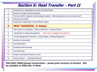
Section 6: Heat Transfer - Part II. ENV-2D02 (2006):Energy Conservation – power point versions of lectures. Will be available on WEB later in Week. Main Objective of the Lecture.

E N D
Section 6: Heat Transfer - Part II ENV-2D02 (2006):Energy Conservation – power point versions of lectures. Will be available on WEB later in Week
Main Objective of the Lecture • To apply the basic ideas of Heat Transfer from previous lecture to estimating the thermal properties of typical building materials. • To provide the tools to allow Heat Loss Estimations from buildings to be made [covered in next lecture ] • >> hence to estimate potential savings.
plaster Internal boundary layer External boundary layer brick Summary of Last Lecture – Key Point • Heat is lost from a building by: • Conduction • But heat is also lost by: • Convection • Radiation from the wall surfaces Resistance to Heat Flow Estimated by where k is conductivity of material d is thickness
Surface Resistance • Analysis of heat flow by convection and radiation is more complex. • Can be approximated in most situations for buildings by additional resistance layers. • Cannot be used if surface temperature are substantially different from surrounds – e.g. a hot water pipe/radiator. Consequences of Boundary Layers • Surface Temperature of window (on room side) is BELOW room temperature - for single glazing it will be about 70C if outside temperature is 0oC and internal temperature is 20oC • External surface temperature will be above surrounding air. • Internal Surface Temperatures are important as they affect Mean Radiant Temperature and hence Thermal Comfort. • External Surface Temperatures can affect weathering properties of bricks.
6.5Internal and External Surface Resistances Typical values for surface resistances (m2oC W-1): Vertical Heat Flow 0.11 for upward flow through floors/roof 0.15 for downward flow through floors Horizontal Heat Flow Rint = 0.123 internal surface Rext = 0.08 sheltered external surface 0.06 normal 0.03 severe • Note: • the orientation of windows is important in heat loss calculations as the external resistance is a significant proportion of the total resistance;
6.6 Resistances of Air-Spaces - thermal conductivity of air-spaces is very small, and heat transfer is mostly by radiation and convection, - values are given in tables, but can be divided generally into two categories:- • unventilated air spaces (or low ventilation) – • resistance is about 0.18. Examples:- • air-space in modern cavity walls, • air-space in double glazing, • air-space between ceiling & underside of felt (post-war houses). • ventilated air spaces – • the resistance is about 0.12. Examples:- • older cavity walls and air-space between ceiling and underside of tiles (pre-war houses).
Internal surface resistance External surface resistance brick brick plaster cavity 6.7 Derivation of 'U'-values for 3 types of wall • Many standard constructions have U-values in Tables • Non-standard constructions do not – including many new types. • Example 1 • 6 components:- • 1) external surface layer • 2) outer brick layer • 3) cavity • 4) inner brick layer • 5) plaster • 6) internal surface layer Fig. 6.6 Heat flow through wall of 1950's construction conductivity of brick = 1.0 Wm-1 oC-1 conductivity of plaster = 0.7 Wm-1 oC-1
6.7 Derivation of 'U'-values for 3 types of wall • Resistance = where k = conductivity d = length of heat flow paths (thickness in this case) • resistance of brick = = 0.11 m2oC W-1 • resistance of plaster = = 0.02 m2oC W-1 • Effective resistances of air spaces are:- internal boundary 0.123 m2 oC W-1 external boundary 0.055 m2 oC W-1 air-cavity 0.18 m2 oC W-1 • So total resistance • = 0.055 + 0.11 + 0.18 + 0.11 + 0.02 + 0.123 • = 0.598 m2 oC W-1 ===========
6.7 Derivation of 'U'-values for 3 types of wall Total Resistance = 0.598 m2oC W-1 • since U = • U = 1.67 W m-2oC -1 • Note: that the external resistance is relatively small < 10% of total resistance U value for walls varies little with exposure normally [only a few per cent at most].
block brick brick plaster cavity Example 2 • As example 1 except that the inner brick leaf is replaced by an aerated block wall i.e. construction used from mid-1960's. • conductivity for aerated block = 0.14 Wm-1 oC-1 • and resistance of such a block = 0.76 m2oC W-1 • replaces the inner brick of original wall, • new resistance = 0.598 + 0.76 - 0.11 = 1.248 m2oC W-1 • so U-value = = 0.80 Wm-2 oC-1 i.e. a 50% saving in the heat lost through the walls of a house.
block brick plaster cavity Filled cavity Example 3 • As example 2 except that cavity is filled with insulation • conductivity of insulation = 0.04 Wm-1 oC-1 • resistance of cavity fill = 0.05 /0.04 = 1.25 m2oC W-1 • replaces the resistance of 0.18 from the air-cavity • New resistance = 1.248 - 0.18 + 1.25 = 2.318 m2oC W-1 • and U-value = = 0.43 Wm-2 oC-1 • i.e. approximately half of the value in example 2 and one quarter of the value in example 1. • [the U-value for a wall with two brick leaves and cavity insulation is 0.60 Wm-2 oC-1].
Example 4: Single Glazing • conductivity of glass = 1 Wm-2 oC-1 • i.e. resistance = 0.003 m2oC W-1 (for 3mm glass) • internal surface resistance = 0.123 • external surface resistance = 0.055 • Thus total resistance = 0.123 + 0.003 + 0.055 • = 0.181 m2oC W-1 • and U-value = 5.5 Wm-2 oC-1 Note • resistance of glass makes very little contribution to the overall resistance • if the external resistance changes (from exposure) then the U-value will also be affected significantly. • [Compare this with the situation for the walls (see note to example 1)].
Temperature Profile through a wall • Example 2 with polystyrene layer on inside • Assumes internal temperature is 20 oC and external temperature is 0oC • Temperature gradient is highest in insulating materials • Greatest in polystyrene layer • External Surface Temperature = 1.17 • If this falls below 0oC – danger of ice forming and causing bricks to crumble. Without polystyrene, surface temperature would be around 1 0C lower And PMV would be approx -0.15 lower
Example 6: Pitched Roof Heat Flow: Internal surface resistance > plasterboard > Loft space > felt > Felt – tile airspace > tiles > External surface resistance >
Example 6: Pitched Roof • Resistance to heat flow • Vertical m2 oC W-1 • Internal surface resistance = 0.11 • Plasterboard = 0.06 • Loft space = 0.18 • Total vertical = 0.35 • Inclined • Felt = 0.11 • Air space felt – tiles = 0.12 • Tiles = 0.04 • External surface = 0.04 • Total Inclined = 0.31 • Total Resistance (if A = 45o) • = 0.35 + 0.31 cos 45 = 0.57 A U – value = 1 / R = 1.75 W m-2oC-1 Pre-war houses do not have felt Some houses in extreme weather areas have boards instead of felt
Example 6: Pitched Roof Simple Way to examine effects of insulation U value without insulation = 1.75W m-2oC-1 Resistance = 1 / 1.75 = 0.57 m2 oC-1 Add 50 mm of insulation conductivity 0.04 Additional resistance = 0.05 / 0.035 = 1.43 New total resistance = 1.43 + 0. 57 = 2.00 New U-Value = 1 / 2.0 = 0.5W m-2 oC-1 With 100 mm New total resistance = 2.86 + 0. 57 = 3.43 New U-Value = 1 / 3.43 = 0.29 W m-2oC-1 With 150 mm New U-Value = 0.21 W m-2 oC-1 A Doubling insulation does not half heat loss
Example 7 Double Glazing • U values 3mm glass = • 4mm glass = • little difference irrespective of what thickness of glass is used. • Double glazing: • U value (3mm glass) = • Note the U value depends on the thickness of the air-space, which is optimum at about 18-20mm.
6.9 Problems associated with thermal bridging Thermal bridging leads to: • cold spots on the internal surfaces • condensation • discolouration where the presence of bridges can be seen. A thermal imaging camera can be used to identify such bridges, but these are often expensive. Insulating the loft in UK houses • Place fibre glass between the joists. • As the thickness of insulation increases problems of thermal bridging appear. • timber joists create a thermal bridge
Insulation (150 mm thick) 400 mm 100 mm joists 50 mm Thermal bridging – an example • In example, insulation occupies 8/9th of space (400/450) • Heat flows are in parallel so use formula • What is effective resistance of joists and insulation? i.e. R = 2.45 cf 3.75 if bridging is ignored
Next Lecture Heat Losses from a House • Need to work out U-values and area for: • Walls • Windows • Roof • Floor • Other sources of heat Loss • Ventilation Remember: • you cannot eliminate heat losses – you can only reduce them. • Heat lost must be replaced by heating device