Download
1 / 20
200 likes | 384 Vues
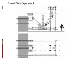
Gusset Plate Experiment. Gusset Plate Experiment. Gusset Plate Experiment. Gusset Plate Experiment. Gusset Plate Experiment. Thickness=1/ 4 in. G1. Gusset Plate Experiment. Thickness=1/ 2 in. G2. Gusset Plate Experiment. Thickness=1/ 4 in. Stub Further in Plate Same # of Bolts. G3.

E N D
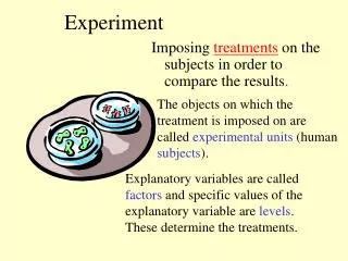
Gusset Plate Experiment Thickness=1/ 4 in. G1
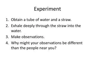
Gusset Plate Experiment Thickness=1/ 2 in. G2
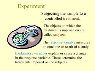
Gusset Plate Experiment Thickness=1/ 4 in. Stub Further in Plate Same # of Bolts G3
Gusset Plate Experiment Thickness=1/ 4 in. Stub Further in Plate Same # of Bolts G3
Gusset Plate Experiment Thickness=1/ 4 in. Same as G1 Same area, EI=EI/10 G4
Gusset Plate Experiment • 8 rosettes • 11 gages • R1-R3: Whitmore section at M4 • G8-G11: Unrestrained edge • Ga1-Ga7, R1: Strain distribution in M4 • R1, R6, R7, R8: Strains at the end of members
Gusset Plate Experiment Whitmore, 1952
If Analyses (FHWA) then
If Analyses (FHWA) then • “When lateral sway of gusset plates is possible, the effective length factor, K, for gusset plates may be taken from Table 2 for Cases (d) (1.0), (e) (2.0), or (f) (2.0), depending on the anticipated buckled shape. When lateral sway of gusset plates is not possible, the effective length factor, K, for gusset plates may be taken from Table 2 for Cases (a)(0.5), (b) (0.7), or (c) (1.0), as appropriate.” (FHWA, 2009) • When is the lateral sway of gusset plate possible ?
Analyses (FE analyses, scripted single plate analyses) • Non Sway Buckling (Euler Buckling) • Sway Buckling • (Euler Buckling) • Yielding of the Plate • Easy, fast and convenient for parametric studies, however since the member stiffness is not introduced, can not capture the sway buckling. • Member stiffness can be introduced as a spring attached to the fastener locations • Calibration according to the experiment is needed
Analyses (FE analyses; Global Model) • Eigen value buckling analyses was conducted and bifurcation buckling was obtained • According to the first mode, initial imperfection was introduced to the model
Analyses (FE analyses; Global Model) • (100% x Thickness), (50% x Thickness), (25% x Thickness) and (12.5% x Thickness) initial imperfection was introduced and gusset plate was analyzed.
Analyses (FE analyses; Global Model) • EI of the member was decreased and same procedure was applied
Analyses (FE analyses; Global Model) • Calibration according to experimental results is needed • Global model can also be scripted