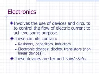
Electronics 101
Electronics 101. Some fundamentals, some applications and some (hopefully) useful tips Jean-François Duval, MIT Media Lab , 11/11/2013. Units. Volt – V – Electric potential Ex.: 24V battery pack Ampere - A – Current. Ex.: I’m passing 10mA through that LED


Electronics 101
E N D
Presentation Transcript
Electronics 101 Some fundamentals, some applications and some (hopefully) useful tips Jean-François Duval, MIT Media Lab, 11/11/2013
Units • Volt – V – Electric potential • Ex.: 24V battery pack • Ampere - A – Current. • Ex.: I’m passing 10mA through that LED • Do not confuse A (current) and Ah (charge). More details later. • Watt – W – Work • This Maxon motor can be used up to 200W (8.33A @ 24V) • Again, do not confuse with Wh (energy) • Farad - F – Capacitance • Ex.: Use a 100nF capacitor between +5V and GND • 1 Farad is huge. Caps > 10000µF are not that common (except for Super Caps, but they are low voltage) • Ohm - Ω – Resistance • Ex.: Use a 10kΩ pull-up on that unused input pin • Henry - H – Inductance • Ex.: this switch mode power supply requires a 100µH inductor
Ohm and kirchhoff • Ohm’s law: V = R*I • Kirchhoff's current law (KCL): The sum of currents in a network of conductors meeting at a point is zero. • Kirchhoff's voltage law (KVL): The voltage drop around a closed loop is 0.
Series and Parallel Resistors • Series: REQ = R1 + R2 + … + Rn • Parallel: 1/REQ = 1/R1 + 1/R2 + … + 1/Rn
Resistive divider, LED current limiter • Voltage divider: VOUT = VIN*(R2/(R1 + R2)) • Ex.: 3.3V supply, R1 = 5kΩ, R2 = 10kΩ. VOUT = 3.3V*(10kΩ/(10kΩ+5kΩ)) = 2.2V • LED resistor: R = (VSUPPLY – VLED)/ILED • Ex.: 3.3V supply, 2V 2mA LED: R = (3.3V – 2V)/2mA = 650Ω
Operational Amplifier • Best reference: “Op Amps For Everyone” by Ron Mancini (TI) (http://www.ti.com/lit/an/slod006b/slod006b.pdf) • The Ideal Op Amp Assumptions:
Operational Amplifier (3) • Op amps can be used for/in/as: • Active filters • Oscillators • Inverting or non-inverting amplifier • Precision rectifier • Integrator • Trans-impedance amplifier (ex.: for photodiodes) • PID loops used to be done only with op amps and passive components
Operational Amplifier (4) • What to be aware of: • Not all op amps are rail-to-rail. Many references advertised as rail-to-rail are only r-r on the output. Read the specs carefully. • Always make sure that your op amp is qualified for the voltage of your system (Is it single supply? Are you trying to use a 5V op amp in a 24V system?) • Bandwidth is one thing, slew-rate is another. It’s especially important to look at the SR if you use square waves. • Ex.: 20kHz sine wave, G=1, Vpeak = 5V: SRMAX = 2*pi*f*Vpeak= 628e3 = 0.63V/µs
Passive filters • Low pass filter: • fc = 1/(2*pi*R*C) • R = 1k, C = 100nF, fc = ? • fc = 1.59kHz • At f=1.59kHz, the gain is -3dB (0.707) • 0.707? G = 10^(GdB/20) = 10^(-3dB/20) = 0.707 • Need a high-pass? Swap R & C • For better performances, look at active filters (filters with an op amp)
BJT Basics • Current controlled device • The Collector Current is proportional to the Base current. • Can be used in the linear region, but nowadays we mostly use it as a switch • Power LED and 2N2222 example NPN PNP
MOSFET basics • Voltage controlled device • Can be used in linear mode, but mostly used for switching applications • When you apply a sufficient voltage to the gate (Vgs), the channel opens • An open channel is like a tiny resistor • Power LED example P-Channel N-Channel
High-side vs low side switch • General rule: • P-CH MOSFET or PNP BJT: High-Side • N-CH MOSFET or NPN: Low-Side
MOSFET, BJT or Relay? • There is no general rule here, but always think about those factors: • If you use PWM, forget about relays • Some MOSFET require a Gate voltage higher than logic power supplies • Old power BJT transistors have really low gain (can be as low as 10). In that case, the base current is non negligible. • Relays are isolated • To drive most (if not all) relays you’ll need a transistor • For low-power stuff, a small logic-gate MOSFET can be used most of the time
Voltage regulators • Two main categories: linear or switching (also known as SMPSor switchers) • Linear: there is a series pass element (usually a transistor). The “unwanted” voltage is converted to heat. Current out = current in. • Ex.: 12V in, 5V out 500mA. Vdrop = (12-5) = 7V. Pout = 2.5W, Pin = 6W. Efficiency: 42%, 3.5W to dissipate in heat. • LDO doesn’t mean lower power! It simply means that you can use it with a lower input voltage • Pros: cheap, small, easy, low noise. Cons: inefficient, generates lots of heat • Switching: a “switch” (usually a MOSFET) chops the input power. An inductor, a diode and a cap filter it. Power in = Power out. Theoretically 100% efficient. • Pros: efficient. Cons: usually bigger, more complex, noisier
Thermal • “My MOSFET is rated for 260A, why would I need a heatsink? I’m only drawing 30A…” • Let’s look at a real part, IRLB3813. Continuous current drain at 25˚C: 260A, RDS(ON) max: 1.95mΩ, Thermal resistance Junction to Ambient (RTJA): 62˚C/W • P = RI² = 1.95mΩ*(30A)² = 1.755W • TJ = Tambient + P*RTJA = 25˚C + 1.755W*62˚C/W = 133.8˚C. Don’t touch it. • For Americans: 272F • (and I’m not including the derating. If you switch it (PWM), the dynamic losses are usually >= static losses) • The same basic math applies to voltage regulators (to everything in fact…)
ESD • Discharge yourself before touching electronics • Always touch boards by the edges
LiPO Battery • Let’s look at a real pack: “Turnigy 5000mAh 6S 20C Lipo Pack” • Each cell will be around 3.7V when fully charged • The minimum voltage is ~3V per cell • 5000mAh means that you can draw 5A for an hour, or 10A for 30 minutes • Faster discharge = less energy • Never over discharge! (Search “lipo fire” on Youtube…)
Misc. Tips, breaking some myths • If you // LEDs, you need 1 resistor per LED (or string) • Always think about power dissipation • MOSFET’s gate doesn’t need current • It’s only true when you reach steady state. At every transition you need to charge/discharge a capacitor. To give you an idea, most gate driver ICs can pump a couple amps in the gate to make it switch as fast as possible! • Keep safety margins in your designs. A 24V MOSFET used to control a 24V motor WILL burn. Why? The inductive spikes can be twice as high as the supply voltage
Useful tools • LTSpice, free SPICE simulator: http://www.linear.com/designtools/software/ • Filter Lab, active filter calculator: http://www.microchip.com/stellent/idcplg?IdcService=SS_GET_PAGE&nodeId=1406&dDocName=en010007&redirects=filterlab • To spec SMPS (and many other circuits), use TI WeBench (used to be NI WeBench): http://www.ti.com/lsds/ti/analog/webench/overview.page?DCMP=PPC_Google_TI&k_clickid=7e5739d4-74cf-8188-3be9-000020f0b88c&247SEM=
What else do you want to know? • How to search on Digikey? • How to design a PCB? • Communication buses? • …?
Sources • Wikipedia: en.wikipedia.org • Random Google Image • Jeelabs: http://jeelabs.org/2012/11/11/low-side-switching/


![PREAMBLE OF ELECTRONICS ENGINEERING [EEC-101/201]](https://cdn3.slideserve.com/5387487/preamble-of-electronics-engineering-eec-101-201-dt.jpg)