Download
1 / 18
180 likes | 357 Vues
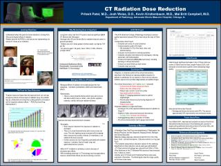
Approach of Hitachi for Dose Rate Reduction. October 12, 2006 Hitachi, Ltd. Trend of Occupational Exposure. Man-Sv = Σ w (Dose rate ×Number of workers ×Working time) w. ☆Dose rate reduction Apply water chemistry control, low Co content material, decontamination and shielding

E N D
Approach of Hitachi for Dose Rate Reduction October 12, 2006 Hitachi, Ltd.
Trend of Occupational Exposure Man-Sv=Σw(Dose rate ×Number of workers ×Working time)w • ☆Dose rate reduction • Apply water chemistry control, low Co content material, decontamination and shielding • In recent year, occupational exposure in Japan is in the highest level in the world. • ☆Suppressing of Number of worker and working time • Apply remote or automatic machine • Review frequency and item of inspection • Apply on line maintenance etc.
Dose Rate Reduction dΓ/dt = δ×C-λΓ Deposition ∝ Deposition × 60Co Conc.(C) Amount(Γ)Rate Coeff.(δ) • How should we reduce the deposition Γ? • 1) To reduce the concentration of radio activities in reactor • water as low as possible • To adopt the methods to suppress the incorporation of • radio-activities in the surface film of pipings. • Best combination of the methods should be selected. It • may be different plant by plant depending on the specific • plant condition.
Dose Rate Reduction Methods dΓ/dt = δ×C-λΓ Deposition ∝ Deposition × 60Co Conc.(C) Amount(Γ)Rate Coeff.(δ) Decontamination (Chemical Decon. etc.) HOP(*1) method -Zn Injection -Low Fe/High Ni Control -Reduction of Surface Roughness (Electric Polishing or Mechanical Polishing) -Alkaline Prefilming -HiF-Coat (Hitachi Ferrite Coating) -Air Oxidation Treatment -H2O2 Preconditioning -RHR Low Temp.Operation 1)Reduction of Parent Nuclei of RI -Low Cobalt Mater. -Wear Resistive Mater. (Hitachi Hyper Valve) 2)Stabilization of RI on Fuel Surface -Improved Fe/Ni Ratio Control -Zn Injection 3)Increase of RWCU Capacity *1)Hydrazine Oxalic Acid, Potassium Permanganate Hitachi Tech.
Dose Rate Reduction Methods HitachiRecommends Construction Phase Operating Phase NWC* HWC** /Adopt low cobalt mater. /Apply Fe/Ni ratio control /Apply chemical decontamination (HOP) /Adopt wear resistive mater. (Hitachi Hyper Valve) /Apply H2O2 precond. after decon. of PLR * NWC:Normal Water Chemistry **HWC:Hydrogen Water Chemistry /Apply surface polishing (for S/S pipings) /Apply HiF-Coat. after decon. of PLR /Apply Alkaline Prefilming (RWCU) /Apply Zn injection Reduction of conc. /Apply RHR low temperature operation Reduction ofδ /Replace to wear resistive mater.
Formation & Deposition Processes of RI Different in process between Fe-control and low Fe control Fe control : By controlling inflow amount of Fe①, suppress the radioactivity concentration③. Low Fe control: By suppressing inflow of Fe①, increase Ni conc. to reduce incorporation of radioact.④ Inflow of 58Co,58Ni, and Fe from FW① Dissolution of 59Co,58Ni (spacer spring etc.) Depo. on fuel surface (by boiling condensation and dry-out) Activation by neutron (59Co(n、γ)60Co、58Ni(n、p)58Co) Redissolution of radioactivity② RW radioactivity conc.③ Deposition on piping surface④ Fuel area Removal at RWCW
Deposition of Radioactivity in Oxide Filmof C/S under NWC RW Fe,Ni ions Crud 2+ 2+ Crud 2+ Co Co Co Recrystl. Dissol. Recrystl. Crystal structures in oxide films (1)α-Fe2O3(Crud) (2)Ni(Co)xFe3-xO4 Base metal Fe ・Oxide film is mainly composed of Fe based oxides. Cr contained film is not formed in this case. ・In this case, as supply of Fe component is abundant compared with S/S, even high Ni concentration cannot prevent 60Co deposition in oxide film.
Concept of Prefilming 図 3 プレフィルミングの概念 Start of Plant Operation プレフィルミング 従来 Oxide Film Thickness Oxide Film Thickness Pre-film 酸化皮膜厚さ プレフィル ミング ( 放射能 ) 放射能付着開始 Oxide Film Thickness and/or Radio Activity Deposition Amount 酸化皮膜厚さ 放射能付着量 酸化皮膜厚さ 放射能付着量 Radio Activity Deposition Amount Radio Activity Deposition Amount 放射能付着量 実運転 Time Time 時間 時間 Ordinary Operation Effect of Prefilming
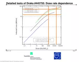
60Co Deposition Rate Coefficient of RWCU System Piping dt δ= 60 Co deposition rate coeff.(cm/h) EFPH • The deposition rate of RWCU carbon steel piping with alkaline prefilming is smaller than that without alkaline prefilming. N.Suzuki ‘An ABWR Water Chemistry Control Design Concept for Low Radiation Exposure and the Operating Experience at the Fist ABWR’9th International Conference on Water Chemistry in Nuclear Reactor Systems (Avignon,Apr.22-26,2002)
Application Experiences of HOP Method ▼Application HWC • HOP method has been applied 20 times for total 13 plants.
Dose Rate Behavior of a US BWR 2500 10 12-15scfm 20 scfm 35 scfm 39.6scfm HWC 2000 Recirc System Decons Pleated Condensate Filters 1500 DZO BRACDoseRate(mR/hr) 1000 500 0 Mar-83 Mar-85 Mar-87 Mar-89 Mar-91 Mar-93 Mar-95 Mar-97 Mar-99 Mar-01 Mar-03 ・After chemical decontamination, dose rate increased under HWC ・Dose rate was decreased by Zn injection R.L.Cowan ‘Modern BWR Chemistry Operating Strategies’10th International Conference on Water Chemistry in Nuclear Reactor Systems (San Francisco,Oct.11-14,2004)
Dose Rate Behavior after Chemical Decontamination is applied US HWC Plants Rebound Rate 2.0 Dose Rate after Decon. 化学除染後リバウンド率(|) = Dose Rate before Decon. Chemical Decon. Rebound Rate (-) 1.0 Japanese NWC Plants 0 -1 2 1 0 Year after Chemical Decom. ・Rebound rate of Japanese NWC plants : 20~100% ・Rebound rate of US HWC plants: 200% and over Dose rate behavior of NWC is different from that of HWC
Deposition Behavior on SUS after Chemical Decontamination HWC、NWC Chemical Decon. Oxide film is removed Oxide film is restored Oxide film is formed Radioactibity ion Crud Deposition Outer Layer Inner Layer Base metal Base metal Base metal NWC:normal water chemistry HWC:hydrogen water chemistry • After the chemical decontamination, the surface of the pipings is restored to the original condition as time elapses. • Under these circumstances, dose rate behaviors of the pipings are expected to be strongly affected by the water chemistry.
Time Dependency of Co-60 Deposition on Specimens 140 HWC ( 0.5ppm H2 injection into feed water) 120 Index 100 80 HWC (1.0ppm H2 injection into feed water) Amount of 60Co deposition(Bq/cm2) 60 40 20 NWC NWC Prefilming* *:200 hours pre exposure in NWC before HWC) 0 0 200 400 600 800 1000 1200 Exposure time(h) • The 60Co deposition on stainless steel under HWC condition is more than that under NWC condtion N. Usui, M. Fuse, H. Hosokawa, S. Uchida., “Effects of Hydrogen Peroxide on Radioactive Cobalt Deposition on Stainless Steel Surface in High Temperature Water”, Nucl. Sci. Technol., . 42, 75 (2005)
Countermeasure to reduce the Dose Rate ー Hi-F Coat ー • Fine magnetite film is formed by Hi-F Coat. • RI deposition on stainless steel is mitigated by this film. Hi-F Coat:Hitachi Ferrite Coating
Countermeasure to reduce the Dose Rate ー Hi-F Coat ー (SEMphotographs) Fine film (Magnetite) is formed by Hi-F Coat Outer Layer(Magnetite) Coating Layer(Magnetite) Inner Layer(Chromate) Deposited Carbon Deposited Carbon Base Metal(SUS304) Base Metal(SUS304) After Hi-F Coat After exposed under NWC condition for 200 h (DO: 300 ppb)
Countermeasure to reduce the Dose Rate ー Hi-F Coat ー (Effect on RI Deposition) Co-60 deposition in HWC could be suppressed by Hi-F Coat Reference(No prefilming) About 1/5 Amount of 60Co deposition(Bq/cm2) NWC Prefilming* Hi-F Coat Exposure time(h) *:200 hours pre exposure in NWC before HWC
Summary • Dose rate reduction methods are reviewed stressing the role of oxide films formed on the surface of the structural components. The control of the oxide film is considered to be an essential factor for a reduction of dose rate of piping. From this point of view, we should further understand the nature of oxide films for developing an effective method of dose rate reduction. • It was found that alkaline prefilming for carbon steel and ferrite coating(Hi-F coat) for recirculation piping were promising methods for dose rate reduction .