Measurements in magnetic field - digression
110 likes | 332 Vues
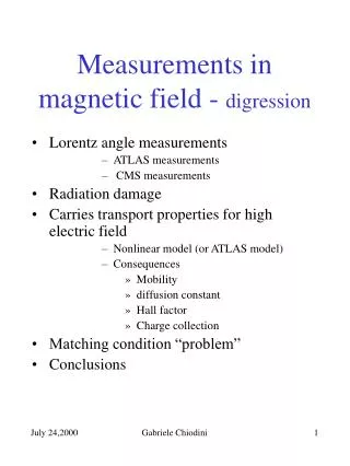
Measurements in magnetic field - digression. Lorentz angle measurements ATLAS measurements CMS measurements Radiation damage Carries transport properties for high electric field Nonlinear model (or ATLAS model) Consequences Mobility diffusion constant Hall factor Charge collection

Measurements in magnetic field - digression
E N D
Presentation Transcript
Measurements in magnetic field - digression • Lorentz angle measurements • ATLAS measurements • CMS measurements • Radiation damage • Carries transport properties for high electric field • Nonlinear model (or ATLAS model) • Consequences • Mobility • diffusion constant • Hall factor • Charge collection • Matching condition “problem” • Conclusions Gabriele Chiodini
Lorentz angle measurementsATLAS and CMS ATLASÞM. Aleppo at Pixel 2000: A measurements of Lorentz angle of rad-hard pixel sensors www.ge.infn.it/Pix2000/slides/aleppo.pdf B=1.4T CMSÞW. Erdmann: The CMS pixel detector Not irradiated Gabriele Chiodini
Lorentz angle measurementsATLAS Gabriele Chiodini
Lorentz angle measurementsCMS “Sensor was irradiated with 6×1034 pions per cm2 at PSI and than stored at 20C for more than one year (also during measurements). Vbias=256 < Vdep and depletion depth=160mm … Charge-sharing between neighbor pixels is observed for the irradiated sensor, but the pattern is not as simple as in the unirradiated case. In a region close to the n-side implants, a small Lorentz angle or reduced charge-sharing is seen. Charge generated deeper in the sensor is deflected with an angle of 28.8±3.6 degs. This measurement was carried out with B=3T. This behavior is not understood in detail yet…” W. Erdmann Gabriele Chiodini
Radiation damage in Si • The doping concentration change the drift mobility when exceeds 1015 impurity per cm3. • “A review of some charge transport properties of silicon” C.Jacoboni, et al. Solid-State Electronics Vol.20, pp 77-89 (1977), pag 82. • Physics of semiconductor device, S.M.Sze, pag.29. The particle fluence excepted in BTeV p-dopes locally the sensor not more than 1013cm-3 than the drift mobility is the same as pure silicon The particle fluence changes the Vdep, the free carrier life time, and so on… Gabriele Chiodini
Charge carriers transport properties for high E – drift mobility It should be T+0.66 • The analytic model is from:“A review of some charge transport properties of silicon” C.Jacoboni, et al. Solid-State Electronics Vol.20, pp 77-89 (1977). • The analytic model reproduce nicely the experimental data. • The e- saturation velocity phenomena is associated to the emission of one optical phonon. • The hole saturation velocity phenomena is nearly observed at E=2×10⁵, but not understood theoretically (this explain Belau et al., and Hijne data). Gabriele Chiodini
Charge carriers transport properties for high E – diffusion constant and rH The measured transverse diffusion constant follows approximately the Einstein relation also at high E. The measured parallel diffusion constant is about 1/3 less than predicted by Einstein relation at high E. Agreement between data and MC simulation which account for the band non-parabolicity C.Jacoboni, et al. Solid-State Electronics pag85 The experimental Hall factor for e- is about 1.15 at room temperature up to Nimpurity=1014cm-3. “Concentration dependence of the Hall factor in n-type silicon” I.G. Kirnas et al. Phys. Stat. Sol. (a) 23, K123 (1974) “Lorentz angle measurements in silicon detectors” W.de Boer et al. Linear Collider Workshop, CERN, Feb. 9, (2000) Lorentz angle measurement for e- and holes by a laser setup and 10T JUMBO Magnet. For B=4T they quote: Lorentz angle = 34 degs(Vbias=40V) and 31 degs(Vbias=100V) Gabriele Chiodini
Charge carriers transport properties for high E – Charge Collection Drift velocity components Trajectory equation and lateral displacement. DX is linear in B but not linear in E(z) Cloud spread DX and dX depend only on the electric field E(z) Gabriele Chiodini
Matching condition “problem” • The nonlinear model gives the mobility reported on the PDB at E=1.3×10³Vcm-1. • It is non clear to me which regime is valid for E going to zero. But this regime concern a negligible layer of the sensor (thickness<<1um) Gabriele Chiodini
Test beam Gabriele Chiodini
Conclusions • Several measurements around the world show that for Vbias > 50V the electron saturation phenomena decrease the charge cloud displacement (or the effective Lorentz angle). • Analytical formulas for mdrift(E)found in literature reproduce the data quite well. • The charge cloud spread depends only on E(z) than his value is not affected by mdrift(E). • Our test beam data in magnetic field also show an effective Lorentz angle much smaller than expected. This can not be explained by adjusting the detector threshold or B in a meaningful range. • Using the nonlinear model an agreement better than 20% with the data can be found (scaling the ATLAS results to our results). Gabriele Chiodini