Magnetic Measurements
430 likes | 1.21k Vues
Magnetic Measurements. Neil Marks, ASTeC, U. of Liverpool, Daresbury Laboratory, Warrington WA4 4AD, U.K. Tel: (44) (0)1925 603191 Fax: (44) (0)1925 603192. Philosophy. To cover methods of measuring flux density but concentrating on the most frequently used methods.

Magnetic Measurements
E N D
Presentation Transcript
Magnetic Measurements Neil Marks, ASTeC, U. of Liverpool, Daresbury Laboratory, Warrington WA4 4AD, U.K. Tel: (44) (0)1925 603191 Fax: (44) (0)1925 603192
Philosophy • To cover methods of measuring flux density but concentrating on the most frequently used methods. • Note that magnetic field H is a representation of the excitation (creation) of the magnetic phenomenon; all measurable effects are driven by the flux density B. • Note that measurement ‘accuracy’ involves three different facets: resolution; repeatability; absolute calibration.
Contents: • 1. Physical effects available for measurement: • a) force on a current carrying conductor; • b) electromagnetic induction; • c) Hall effect (special case of (a)); • d) nuclear magnetic resonance. • 2. Practical applications: • a) point-by-point measurements; • b) rotating coil methods; • c) traversing coils.
1a) Force on a current carrying conductor • F = B I • where: F is force per unit length; • B is flux density; • I is current. • Advantages: • integrates along wire; • I can be accurately controlled and measured. • Disadvantages: • not suitable for an absolute measurement; • measurement of F is not very highly accurate; • therefore not suitable for general measurements.
Use in spectrometry specialised trajectory tracing in experimental magnets: ‘Floating wire’ technique - wire is kept under constant tension T and exit point is measured for different entry points. T B I T
1 b) Electromagnetic induction • curl E = - B / t; V = B An sin wt. • (V is induced voltage; B is flux density; A is coil area; n is coil turns. • Advantages: • V can be accurately measured; • Gives B integrated over the coil area. • Disadvantages: • / t must be constant (but see later); • absolute accuracy limited by error in value of A; • Can be sufficiently accurate to give absolute measurements but best for relative measurements. • Used: • standard measurements of accelerator magnets; • transfer standards;
1 c) Hall effect • Special case of force on a • moving charges; a metal • (or semiconductor) with a • current flowing at right • angles to the field develops • a voltage in the third plane: • V = - R ( J x B ) a • where: V is induced voltage; B is field; • J is current density in material; • a is width in direction of V • R is the 'Hall Coefficient' ( fn of temperature ): • R = fn (a,q); • q is temperature; a is temperature coefficient.
Hall effect (cont.) • Advantages: • small light probe; • easily portable/moved; • J, V accurately measurable – good resolution, repeatability; • covers a very broad range of B; • works in non-uniform field. • Disadvantages: • q must be controlled measured/compensated; • R and a must be known accurately. • Used: • commercial portable magnetometers; • point-by-point measurements;
1 d) Nuclear magnetic resonance. • In an external magnetic field, nuclei with a magnetic moment precess around the field at the Larmor precession frequency: • n (g /2 p) B; • where: n is the precession frequency; • g is the gyromagnetic ratio of the nucleus; • B is external field. • A radio-frequency e-m field applied to the material at this frequency will produce a change in the orientation of the spin angular momentum of the nucleus, which will ‘flip’, absorbing a quantum of energy. This can be detected and the r.f. frequency measured to give the precession frequency and hence measure the field.
Spin transition. • The ‘spin flip’ in a nucleus: Example: for the proton (H nucleus): with B = 1 T; n= 42.6 MHz.
N.M.R. (cont.) • Disadvantages: • probe is large size (~ 1cm); • resonance only detectable in high homogeneous B; • apparatus works over limited B range, (frequency n is too low at low B); • equipment is expensive; • Advantages: • only dependent on nuclear phenomena - not influenced by external conditions; • very sharp resonance; • frequency is measured to very high accuracy (1:106); • used at high/very high B. • Use: • most accurate measurement system available; • commercially available; • absolute measurement of fields; • calibration of other equipment.
Practical Applications – 2a Point by point • A probe is traversed in 2 or 3 planes with B measured by a Hall plate at each point to build up a 2/3 dimensional map. Superseded by rotating coils for multi-poles, but still the method of choice for a small number of high quality dipoles. (It is too slow for a production series)
Modern Hall Bench used at DL for insertion magnets. • Hall Probe MPT-141-3m (Group 3); • Tesla-meter DTM-141-DG “ • Longitudinal Range 1400 mm • Horizontal Range 200 mm • Vertical Range 100 mm • Longitudinal Resolution (z) 1 mm • Horizontal Resolution (x) 0.5 mm • Vertical Resolution (y) 0.5 mm • Nominal Longitudinal Velocity 1 mm/s • Maximum Calibrated Field 2.2 T • Hall Probe Precision ± 0.01 % • Hall Probe Resolution 0.05 mT • Temperature Stability ± 10 ppm/°C
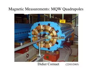
2 b – Rotating Coil systems. • Magnets can be measured using rotating coil systems; suitable for straight dipoles and multi-poles (quadrupoles and sextupoles). • This technique provides the capability of measuring: • amplitude; • phase; • integrated through the magnet (inc end fringe fields). • of each harmonic present, up to n ~ 20 or higher; • and: • magnetic centre (x and y); • angular alignment (roll, pitch and yaw)
-C +C +C -C -C +C The Rotating Coil A coil continuously rotating (frequency w) would cut the radial field and generate a voltage the sum of all the harmonics present in the magnet: dipole: V = sin wt quad: V = sin 2 wt Etc. sextupole: V = sin 3 wt
Continuous rotation • The coil (as shown) is rotated rapidly in the magnetic field; the induced voltage is analysed with a harmonic analyser. • Induced voltage : Continuous rotation is now regarded as a primitive method!
Problems with continuous rotation • Sliding contacts: generate noise – obscures small higher order harmonics; • Irregular rotation: (wow) generates spurious harmonic signals; • Transverse oscillation • of coil: (whip-lash) generates noise and spurious harmonics. • Solution developed at CERN to measure the LEP multi-pole magnets – SEE NEXT SLIDE.
Mode of operation • Rotation and data processing: • windings are hard wired to detection equipment and cylinders will make ~2 revolutions in total; • an angular encoder is mounted on the rotation shaft; • the output voltage is converted to frequency and integrated w.r.t. angle, so eliminating any /t effects; • integrated signal is Fourier analysed digitally, giving harmonic amplitudes and phases. Specification: relative accuracy of integrated field ±3x10⁻⁴; angular phase accuracy ±0.2 mrad; lateral positioning of magnet centre ±0.03 mm; accuracy of multi-pole components ±3x10⁻⁴
Rotating coil configurations • Multiple windings at different radii (r) and with different numbers of turns (n) are combined to cancel out harmonics, providing greater sensitivity to others: All harmonics All odd harmonics, 1,3,5 etc. Dipole and quadrupole rejected.
Test data used to judge Diamond quads(acknowledgement to Tesla Engineering for spread-sheet developed for Quad measurement)
Coil Magnet on test. Reference magnet (prototype) 2 c) Traversing coils • Used in curved dipoles -similar method of data acquisition as used in a rotating coil. The coil (with multiple radial windings) is traversed from the reference to the test magnet; voltage from each winding is integrated; variation from zero in the integrated volts, after the traversal, indicates variations from the reference magnet total flux vs radius values, which are known.