Download
1 / 16
460 likes | 1.5k Vues
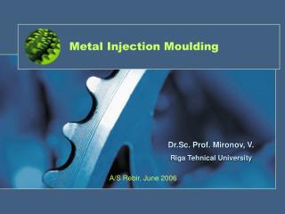
Metal Injection Moulding. Dr.Sc. Prof. Mironov, V. Riga Tehnical University. A/S Rebir, June 2006. Product and technology. Diagram of a fully continuous production line showing the three main process stages: injection molding, debinding and sintering. MiM from BASF.

E N D
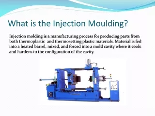
Metal Injection Moulding Dr.Sc. Prof. Mironov, V. Riga Tehnical University A/S Rebir, June 2006
Product and technology Diagram of a fully continuous production line showing the three main process stages: injection molding, debinding and sintering.
MiM from BASF MiM is a process-ready granulate, consisting of metal or ceramic powder and a polyacetal-based binder system. The injection molded components possess a high green strength, permitting fully automated injection molding even of components with complex geometries. Catalytic debinding is particularly rapid, and allows processes to be operated continuously, with the associated economic benefits for high volumes. Furnaces from respected manufacturers are available for continuous or batch sintering. BASF has developed a number of different Catamold® types, which have become a de-facto standard on the market.
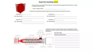
Catamold® Ready-to-use granules containing powder and binders
Injection Molding The part is molded. (Green part)
Debinding The binder is removed. (Brown part)
Sintering High temperatures give the part its final size and properties. (Sintered part)
Hydraulic coupling This angular part composed of 316L is a hydraulic coupling for small cylinders in a convertible. This coupling part employed in hydraulic systems has been produced up to now by soldering the two end pieces onto a prefabricated tube and then bending it. Using Catamold technology it is possible to achieve the final shape in one forming step and to lower the overall fitting height markedly. Soldering and turning of the end pieces are also rendered superfluous.
Combustion chamber In the case of this combustion chamber for auxiliary heating systems made from austenite 316LG Catamold technology has substituted precision casting as the manufacturing process. Apart from distinctly lower-cost production it was also possible in this way to replicate engineering details which were not possible in precision casting. Fine structures, cross holes and blind holes could be very effectively formed by using the Catamold technique.
Consumer generating reliability Cogs These small cogs were manufactured from an extremely fine grained pure iron powder and nickel-plated after sintering.
Mechanical assuring safety Locking disk The locking disk made of 17-4PH temperable stainless steel is a functional part of a lock mechanism designed to prevent unauthorized opening of machine tools. The part is exposed to high mechanical loads, especially on the outer webs. By means of Catamold technology it is possible to make the disk very thin without any need for additional mechanical operations.
Control valve This component was earlier composed of four separately manufactured segments which had to be positioned and then soldered together. Using the Catamold process the component can be produced as compact finished part in essentially three process steps. The material used is 316L austenitic stainless steel, which offers superior strength and corrosion resistance to that of chrome-plated brass.