Solar Thermal Energy Generation
460 likes | 711 Vues
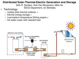
Solar Thermal Energy Generation. Group 7 Andy Bryan (EE), Beau Eason (EE), Rob Giffin (EE), Sean Rauchfuss (EE) Funded by Progress Energy. Motivation. The world needs new reliable sources of energy

Solar Thermal Energy Generation
E N D
Presentation Transcript
Solar Thermal Energy Generation Group 7 Andy Bryan (EE), Beau Eason (EE), Rob Giffin(EE), Sean Rauchfuss (EE) Funded by Progress Energy
Motivation • The world needs new reliable sources of energy • Current energy supply is based mainly on fossil fuels and natural gas which have a limited supply • Finding a new energy source which is renewable, such as solar, would be best • Because of this need, a lot of money can potentially made
Project Goals & Objectives • Utilize an energy source which is free and abundant • Be able to store the generated energy as electric potential • Prove that the concept can work with a functioning prototype
Specifications • The system is to weigh no more than 50 kilograms and is to occupy a volume no greater than 2 meter3 • The system is to be capable of operating continuously under ideal conditions for at least a 2 hour period • A 12V supply battery will be able to properly power the control system • The generator output will be capable of efficiently and safely charging a 12V battery
Specifications • The tracking system will be able to keep the focal of the Fresnel lens precisely on the heat element of the Stirling engine as to avoid damage to other parts of the system and to maximize energy generation • Fresnel lens will be capable of producing focal point with enough heat to properly operate Stirling cycle engine
Specifications • A microcontroller will control the tracking system as well as be responsible for battery and charge control management • The system will utilize two 12V batteries that will be interchangeable in function. The microcontroller will be responsible for switching between battery functions • Switching regulators will be used to provide proper power for the microcontroller and tracking system motors from the 12V battery
Fresnel Lens • Reach temperature of up to 2000 °F • Requires precise alignment of focal point • Chose a 40”x28” spot lens
Stirling Engine • Based on Carnot cycle of thermodynamics 2 3 1 4
Generator • Rated up to 24 VDC • Low starting / running torque • Brush permanent magnet • Cost effective • Typically outputs 5-7VDC
Boost Regulator • Used to step up 5-7VDC generator output to 12V needed to charge battery • Used ISL98012 • Chosen for step up capabilities
Charge Controller • BQ24450 • 12V charge controller • Max output voltage 13.8 • High Efficiency • Safety From boost Regulator
Charge Battery • Leoch LP12-6-FI • Chemistry: Lead Acid • Voltage: 12 • Capacity: 7.00 Ah • Rating: 84 Whr • Cells: 6 2.6” 3.7” 6”
Altitude Azimuth Dual Axis Solar Tracking • Meets accuracy need of lens and engine • Maintains central point where focal will always be
Lens Support Assembly • Contains Lens and Sensor Array • Rotates about Lens focal point (30°- 90°) • Interfaces with an actuator • Pins to Revolving Frame Assembly
Revolving Frame Assembly • Contains Actuator bracket, LSA support arms, and wheels • Rotates about central axis (0° - 360°) • Interfaces with a geared stepping motor on base platform
Base Platform Assembly • Contains Stirling Cycle Heat Engine, Generator, Stepper Motor, Batteries, Control Box • Raised inside platform which keeps wheels on RFA aligned properly
Sun light Sensor A Sensor B Altitude Up Sensor C Sensor D Azimuth Left Azimuth Right Altitude Down The finalized design of the solar tracking sensor array. To control system Photo detector Solar Sensing Block diagram of how sunlight is communicated to the control system
Using LEDs as Light Detectors • No input voltage required • Output • Direct sunlight=1.5V • Partial sunlight=0.6V • Ambient Light=.02V
Microcontroller MSP430 • This the target board being used • The particular MSP430 being used is the MSP430F2224 • Chosen because of need for several I/O pins as well as analog to digital conversion
Software • During most of the operation cycle no control will be needed • This allows us to utilize the MSP430’s low power modes (LMPX) • An internal clock will be used for the delay between sensor reads
Stepper Motor • Used for azimuth angle adjustments • HT23-260-4 • 260 Oz In. Hybrid • 1.8° /200 Steps Per Rev. • 2.5 Amps Current Per Phase • 4-wire Bi-polar
Stepper motor control • This shows TI’s DRV8412 configured to run a stepper motor • Utilizing this IC makes controlling the stepper motor much easier • Lots of application documentation available
Stepper motor issues • Problems with driver circuit on PCB • Spent over a week attempting to fix IC • Could never get necessary power to charge stepper motor windings • Eventually had to find a new solution to problem due to time issues
Resolution - HBridge • We constructed an Hbridge to power the stepper motor • After much testing the stepper motor we could still not operate the stepper motor • Solution was to change to a geared servo motor • A separate Hbridge is being used to control the actuator
Actuator • Used for altitude angle adjustments • FA-PO-150-12-12 • Built in limit switches (non moveable) • Aluminum case • Two clevis mount points, one on each end (uses our MB1 brackets) • 10K ohm potentiometer built in
Supply Battery • Leoch LP12-6-FI • Same as charge battery • Function switchable by microcontroller 2.6” 3.7” 6”
Tracking System Power • MSP430- 3V • ISL8502 buck regulator • Actuator- 3V • ISL8502 buck regulator • Step controller - 12V • Straight from supply battery
Tracking System Power Issues • ISL8502 buck regulators operated correctly during initial testing • Burnt out during system testing and no longer produce useable voltage
Battery Function Switching • Utilizes 4 LTC4412 low loss power path controllers • Function similarly to logic MUX and allow for safe switching of battery function
PCB Layout Boost Regulator Buck Regulators Charge Controller Power Switches Step Controller MSP430
Testing • Each component tested and operate correctly • Tracking system failed during system testing • Charging system operates correctly for 30 continuous minutes • Able to slowly charge the 12 V battery • Max power is 5 Watts
Project Challenges • Large amount of Mechanical Engineering to overcome • Aluminum welding was prohibitively expensive • Inexperience in PCB design • Inexperience in ordering parts • Power issues
To do • Update budget • Update msp430 info • Add stirling cycle dimensions • Proofread