Download
1 / 30
300 likes | 408 Vues
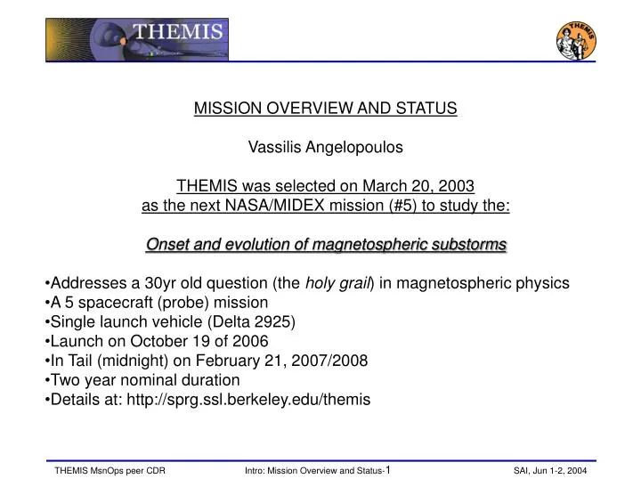
MISSION OVERVIEW AND STATUS Vassilis Angelopoulos THEMIS was selected on March 20, 2003 as the next NASA/MIDEX mission (#5) to study the: Onset and evolution of magnetospheric substorms Addresses a 30yr old question (the holy grail ) in magnetospheric physics A 5 spacecraft (probe) mission

E N D
MISSION OVERVIEW AND STATUS • Vassilis Angelopoulos • THEMIS was selected on March 20, 2003 • as the next NASA/MIDEX mission (#5) to study the: • Onset and evolution of magnetospheric substorms • Addresses a 30yr old question (the holy grail) in magnetospheric physics • A 5 spacecraft (probe) mission • Single launch vehicle (Delta 2925) • Launch on October 19 of 2006 • In Tail (midnight) on February 21, 2007/2008 • Two year nominal duration • Details at: http://sprg.ssl.berkeley.edu/themis
Outline • Covered in this presentation • Mission objectives • Redundancy and resilience • Overview of launch and placement • RCS, ACS and Operational modes
Status • PDR – peer: Oct 8/9/15/16, 2003, Mission: Nov 13-14, 2003 • Confirmation Readiness Review – [Original: Dec’03] GSFC, Feb 4, 2004 • Confirmation Review – [Orig. Dec’03] Attempt: HQ, Mar 4, 2004 (Aborted) • Confirmation: April 22, 2004 • GSFC direction to further reduce I&T schedule risk • Developed better I&T flow, validated by GSFC Engineering • Developed 2 month slack in I&T flow, pushing launch to 10/2006 (slot=10/19/2006) • Added P1 end magnetics EMC/EMI verification and calibration test • Added pressurant tank: increased mission deltaV to help: • mass posture (refocus bus on instrument hosting); • bus development schedule; • a compressed ascend and commissioning scenario • Lost dawn sector conjunctions; but kept ascend schedule contingency • Design work kept-on full steam (Instr. and BAU ETU production & testing) • Test plans being detailed; test GSE/software/adl.TV tanks being built • Instr. ETU vibration this week, electrical tests ongoing; TV tests ongoing • Instrument ETU I&T: July 2004. • MCDR followed by flight instrument fabrication start: Jun 14, 2004.
TIME HISTORY OF EVENTS AND MACROSCALE INTERACTIONS DURING SUBSTORMS (THEMIS) Science Team RESOLVING THE PHYSICS OF ONSET AND EVOLUTION OF SUBSTORMS Principal Investigator Vassilis Angelopoulos, UCB Program Manager Peter Harvey, UCB Mission Operations Manager Manfred Bester, UCB GSFC technical partnership Mark Beckman, MESA (former GN&C) Industrial Partner SWALES Aerospace, Inc., Beltsville MD
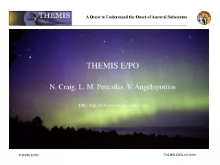
Auroral eruptions and substorms …are a manifestation ofmagnetospheric substorms Auroral eruptions… SOLARWIND Aurora MAGNETOSPHERE EQUATORIAL PLANE
Most important science resultand its science impact • Answers how substorms operate • Explains how magnetospheres process solar wind energy • Explains how auroras erupt ASTROSPHERE GALACTIC CONFINEMENT SUBSTORM RECURRENCE: MERCURY: 10 min EARTH: 3.75 hrs JUPITER: days
: Ground Based Observatory Mission elements Probe conjunctions along Sun-Earth line recur once per 4 days over North America. … while THEMIS’s space-based probes determine onset of Current Disruption and Reconnection each within <10s. Ground based observatories completely cover North American sector; determine auroral breakup within 1-3s …
First bonus: What producesstorm-time “killer” MeV electrons? Affect satellites and humans in space ANIK telecommunicationsatellites lost for days to weeksduring space storm • Source: • Radially inward diffusion? • Wave acceleration at radiation belt? • THEMIS: • Tracks radial motion of electrons • Measures source and diffusion • Frequent crossings • Measures E, B waves locally
Second bonus: What controls efficiencyof solar wind – magnetosphere coupling? • Important for solar wind energy transfer in Geospace • Need to determine how: • Localized pristine solar wind features… • …interact with magnetosphere • THEMIS: • Alignments track evolution of solar wind • Inner probes determine entry type/size
THEMIS is unique and timely • Solves major long-standing question in magnetospheric physics (NAS) • Self-sufficient, ideally complements current SEC line • Global context for Cluster (2006/7), MMS (2010), LWS (Rad. Belt Storm Probes: 2012) • A scientific and technological pathfinder for future SEC missions • Pre-requisite to Space Weather prediction • Identifies causal relationships for MagCon • Low cost highly integrated probes inanticipation of future Constellations • Inspires K-12 students • Hands-on involvement of high-schoolstudents: ground magnetometer curators • First University-managedmulti-satellite project • Expands NASA partnership with Academia • Trains scientific, technological and industrial workforce of future
Outline • Covered in this presentation • Mission objectives • Redundancy and resilience • Overview of launch and placement • RCS, ACS and Operational modes
Selected instruments built en masse before Identical instrumentation provides high science margins and fault tolerance • Instrument redundancy: • SST-ESA energy overlap • FGM-SCM frequency overlap • P1/P2 redundant instrumentation (only directional flux needed in one of two). • Each probe has: • 1FGM • 1ESA (i/e) • 2SSTh (2heads, i/e) • 1SCM • 4EFIs (4spin plane) • 2EFIa (2axials)
Probe conjunctions well understood • BASELINE: >10 substorms achieved w/ 5 probes in 2 yrs & 20% margin. • MINIMUM: >5 substorms achieved in 1yr w/ 4 probes (at margin >2). • computations include lunar, solar, drag, J2 terms • dYP1/2/3/4/5<±2RE; dZP3,4,5/NS<±2RE; dZP1,2/NS<±5RE • Ascent design is optimal for science • maximizes conjunctions, minimizes shadows • … immune to launch insertion errors • small, piece-wise DVs increase placement fidelity • … and immune to probe insertion errors. • Can withstand insertion error of dV=40cm/s on any probe (dV control is 100 times better; knowledge requirement is 3 times better, capability is >10times better) Actual conjunction times in 1st year
Descope list and science-relatedrisk mitigation factors • Re-positioning allows recovery from failure of critical instruments on some probes • Graceful degradation results from partial or even full instrument failures • Instrument frequency and energy range overlaps • Complete backup option for EFI radials (need 2 in most probes but have 4) • Relaxed measurement requirements (1nT absolute is not permitted to drive team, but rather a nicety) • Substorms come in wide variety; can still see large ones with degraded instruments • Minimum mission can be accomplished with a reduced set of spacecraft requirements • EMC and ESC requirements important for baseline but less severe for minimum mission • Observation strategy can be tuned to power loss (turn-on/off) and thermal constraints (tip-over/back) • Fuel and mass margins for 1st year (minimum) are 30% larger than for a two year (baseline) mission
Outline • Covered in this presentation • Mission objectives • Redundancy and resilience • Overview of launch and placement • RCS, ACS and Operational modes
Standard Delta 10 ft. Fairing Static Envelope 3712 PAF Star 48 3rd Stage THEMIS Launch Configuration Delta II Launch From KSC • Dedicated Delta 7925-10 • 10’ Composite Fairing required to accommodate five Probes on the Probe Carrier in the “Wedding Cake” configuration • PC stays attached to Delta 3rd stage after probe dispense minimizing orbital debris • Each probe dispense from the PCA is coordinated with but independent of the other probes • No single probe anomaly precludes dispense of remaining probes • Boeing provided ordnance fired from 3rd stage blows all clampbands to initiate separation Probe Carrier Assembly (PCA = 5 Probes + Probe Carrier) on L/V Probe Carrier Assembly (PCA) on Delta 3rd Stage
EFIs EFIa SCM ESA BGS SST Operations UCB FGM Tspin=3s Instrument I&T UCB Ground Mission overview: Fault-tolerant design hasconstellation and instrument redundancy D2925-10 @ CCAS Encapsulation & launch Mission I&T Swales Probe instruments: ESA: Thermal plasma (UCB)SST: Super-thermal plasma (UCB)FGM: Low frequency magnetic field (TUBS/IWF) SCM: High frequency magnetic field (CETP) EFI: Electric field (UCB, LASP)
Outline • Covered in this presentation • Mission objectives • Redundancy and resilience • Overview of launch and placement • RCS, ACS and Operational modes
2x Top Solar Panels Axial EFIBooms Top Deck SCM Boom 4x Side Solar Panels FGM Boom ESA 4x Radial EFIs 2x SSTs 2x Tang. Thruster RCS Fill / Drain Valves Bus Overview Antenna • Probe bus is a single string design with selected redundancy • Power positive in all attitudes with instruments off (launch, safe hold modes) • Passive thermal design using MLI and thermostatically controlled heaters tolerant of longest shadows (3 hours) • Spin stabilized probes point within 13° of ecliptic south and have inherently stable thermal environment • S-Band communication system always in view of earth every orbit at nominal attitude.In view for greatest part of orbit in any attitude • Passive spin stability achieved in all nominal and off-nominal conditions • Monoprop blow down RCS (propulsion) system is self balancing on orbit Sun Senor IRU
Reaction Control System (RCS): A Hydrazine Orbit/Attitude Control System • Blowdown N2H4 system design • Two Interconnected tanks • Lightweight, High Performance System • Robust, self-balancing fuel management (as on ISEE, ACE) • Components flown on dozens of missions, integrated by Aerojet • Readily Available Components • Arde Inconel propellant tanks on order • Carleton P/N 7149 pressurant tank from ST5 • All other components are off the shelf • Robust • Thruster arrangement provides for partial redundant function with degraded performance • Meets all Range Safety Requirements • Heritage design based on ISEE-3 and ACE
Propulsion System RecentUpgrade for Additional Fuel • Tanks are launched 93% full • Initial blowdown occurs quickly • One time actuation of pressurant tank • Repress back to full pressure • Larger volume depressurizes slowly
ACS sensors • Sun Sensor provides spin pulse and elevation angle • FGM science sensor doubles up as TAM ACS sensor • Two Solid State Gyros (Inertial Reference Units) for tactical use; provide Wx, Wy
RCS operational modes • Slew/precession control • Sun synchronous thrusting • Major circle reor performed bypiece-wise continuous Rhumb line reor • Spin up/down • Continuous and/or sun synchronous • Axial thrust • Continuous • Side thrust • Sun synchronous thrusting • None of the above (i.e., no thrusting) = “safe mode” • Fault protection to return to “none of the above” if anomaly is detected • Thrusters commanded off under following conditions: • Sun aspect angle out of bounds • Spin rate out of bounds • Thruster control electronics Watch Dog Timer time out • Processor reboot
Major relevant design changes since PDR • Repress system (pressurant tank) • Can carry 9kg more fuel by filling up tanks to 93% • Spin axis near ecliptic South (was near-North) • Saves 4.5kg of fuel or 120m/s equivalent delta V; thermal solution benefits too. • Near axial thrusting for main inclination change after boom deployment • Accept beta inefficiency and correct resultant plane changes at apogee or perigee • Target Orbit Tuned: Reduced prg, increased inc, new 3s data • PRG: 600km->305km: Now 2nd and 3rd stage are ODA compliant, at ~4% dV cost. • INC: Inc. 9deg->9.5 Increased launch mass by 20kg (800kg -> 828kg); adl. 1% dV. • Validated stable apogee for >2mo., but lunar phasing with UT, RAAN, APG dispersions still TBD • APG: new 3s data (apg uncertainty 2400km -> 7400km) at 12% dV cost. • NEW baseline dV increased: 566m/s -> 628m/s. • ACS: Reor along major circle via Rhumb line sections • Sufficient command load capability to account for up to 20 reor sections • ACS: Transmit gyro data to ground, integrate angles near real time • Simpler to implement, sufficient time to abort, sun sensor still does RT limit checks
Baseline L1 Req’s pertaining to orbit design • S-2 Current Disruption Onset Time • Determine current disruption onset time with t_res<30s, using two near-equatorial (within 2Re of magnetic equator) probes, near the anticipated current disruption site (~8-10 Re). Current disruption onset is determined by remote sensing the expansion of the heated plasma via superthermal ion flux measurements at probes within +/-2Re of the measured substorm meridian and the anticipated altitude of the current disruption. • S-3 Reconnection Onset Time • Determine reconnection onset time with t_res<30s, using two near-equatorial (within 5Re of magnetic equator) probes, bracketing the anticipated reconnection site (20-25Re). Reconnection onset is determined by measuring the time of arrival of superthermal ions and electrons from the reconnection site, within dY=+/-2Re of the substorm meridian and within <10Re from the anticipated altitude of the reconnection site. ….. • S-4 Simultaneous Observations • Obtain simultaneous observations of: substorm onset and meridian (ground), current disruption onset and reconnection onset for >10 substorms in the prime observation season (September-April). Given an average 3.75hr substorm recurrence in the target tail season, a 2Re width of the substorm meridian, a 1Re requirement on probe proximity to the substorm meridian (of width 2Re) and a 20Re width of the tail in which substorms can occur, this translates to a yield of 1 useful substorm event per 18.75hrs of probe alignments, i.e, a requirement of >188hrs of four-probe alignments within dY=+/-2Re.
… continued: Baseline L1 Requirements • S-6 Earthward Flows • Track between probes the earthward ion flows (400km/s) from the reconnection site and the tailward moving rarefaction wave in the magnetic field, and ion plasma pressure (motion at 1600km/s) with sufficient precision (dV/V=10% or V within 50km/s whichever is larger, dB/B=10%, or B within 1nT whichever is larger, dP/P=10%, or P within 0.1nPa whichever is larger) to ascertain macroscale coupling between current disruption and reconnection site during >10 substorm onsets (>188hrs of four-probes aligned within dY of +-2Re). • S-7 Pressure Gradients • Determine the radial and cross-current-sheet pressure gradients (anticipated dP/dR, dP/dZ ~0.1nPa/Re) and ion flow vorticity/deceleration with probe measurement accuracy of 50km/s/Re, over typical inter-probe conjunctions in dR and dZ of 1Re, each during >10 onsets. The convective component of the ion flow is determined at 8-10Re by measurements of the 2D electric field (spin-plane to within +-30degrees of ecliptic, with dE/E=10% or 1mV/m accuracy whichever is larger) assuming the plasma approximation at t_res<30s. • S-8 Cross-Current Sheet changes • Determine the cross-current-sheet current change near the current disruption region (+/-2Re of meridian, +-2Re of measured current disruption region) at substorm onset from a pair of Z-separated probes using the planar current sheet approximation with relative (interprobe) resolution and interorbit (~12hrs) stability of 0.2nT. • S-10 Cross-Tail Pairs • Determine the presence, amplitude, and wavelength of field-line resonances, Kelvin-Helmholz waves and ballooning waves on cross-tail pairs (dY=0.5-10Re) with t_res<10s measurements of B, P and V for >10 substorm onsets.
Minimum L1 Req’s pertaining to orbit design • 4.1.2.2 Current Disruption Onset Time • Determine current disruption onset time with t_res<30s, using two near-equatorial (within 2Re of magnetic equator) probes, near the anticipated current disruption site (~8-10 Re). Current disruption onset is determined by remote sensing the expansion of the heated plasma via superthermal ion flux measurements at probes within +/-2Re of the measured substorm meridian and the anticipated altitude of the current disruption. • 4.1.2.3 Reconnection Onset Time • Determine reconnection onset time with t_res<30s, using two near-equatorial (within 5Re of magnetic equator) probes, bracketing the anticipated reconnection site (20-25Re). Reconnection onset is determined by measuring the time of arrival of superthermal ions and electrons from the reconnection site, within dY=+/-2Re of the substorm meridian and within <10Re from the anticipated altitude of the reconnection site. ….. • 4.1.2.4 Simultaneous Observations • Obtain simultaneous observations of: substorm onset and meridian (ground), current disruption onset and reconnection onset for >5 substorms in the prime observation season (September-April). Substorm statistics discussed in S-4 point to a requirement of >94hrs of four probe alignments. • Lifetime • THEMIS instrument and spacecraft shall be designed for at least a 2-yr lifetime • Launch • THEMIS will be launched into an orbit with Ra=12Re, Rp=1.1Re and INC=9.5deg, prior to 03/2007. • Launch window = 40 min • Prefered (not required) launch season = August 2006 +/- 2 months (now October 19, 2006).