Advanced Audio Data Conversion Techniques: Oversampling and Noise Shaping
Explore the principles of oversampling and noise shaping in audio data conversion, including the benefits of reducing quantization noise and optimizing digital audio quality with state-of-the-art converters.

Advanced Audio Data Conversion Techniques: Oversampling and Noise Shaping
E N D
Presentation Transcript
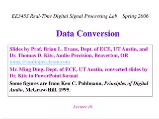
Slides by Prof. Brian L. Evans, Dept. of ECE, UT Austin, and Dr. Thomas D. Kite (Audio Precision, Beaverton, OR tomk@audioprecision.com) Dr. Ming Ding, when he was at the Dept. of ECE, UT Austin, converted slides by Dr. Kite to PowerPoint format Some figures are from Ken C. Pohlmann, Principles of Digital Audio, McGraw-Hill, 1995. Data Conversion
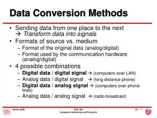
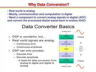
Solutions • Oversampling eases analog filter design Also creates spectrum to put noise at inaudible frequencies • Add dither (noise) at quantizer input Breaks up harmonics (idle tones) caused by quantization • Shape quantization noise into high frequencies Auditory system is less sensitive at higher frequencies • State-of-the-art in 20-bit/24-bit audio converters Oversampling 64x 256x 512x Quantization 8 bits 6 bits 5 bits Additive dither 2-bit PDF 2-bit PDF 2-bit PDF Noise shaping 5th / 7th order 5th / 7th order 5th / 7th order Dynamic range 110 dB 120 dB 120 dB
Input to Upsampler by 4 16 bits44.1 kHz 28 bits176.4 kHz 16 bits176.4 kHz FIR Filter 4 n 1 2 Output of Upsampler by 4 Digital 4x Oversampling Filter n’ 1 2 3 4 5 6 7 8 Output of FIR Filter n’ 1 2 3 4 5 6 7 8 Digital 4x Oversampling Filter • Upsampling by 4 (denoted by 4) For each input sample, output the inputsample followed by three zeros Four times the samples on output as input Increases sampling rate by factor of 4 • FIR filter performs interpolation Multiplying 16-bit data and 8-bit coefficient: 24-bit result Adding two 24-bit numbers: 25-bit result Adding 16 24-bit numbers: 28-bit result
176 kHz Oversampling Plus Noise Shaping Pohlmann Fig. 4-17 Noise shaping following oversampling decreases in-band quantization error. A. Simple noise-shaping loop. B. Noise shaping suppresses noise in the audio band; boosted noise outside the audio band is filtered out.
Oversampling and Noise Shaping Pohlmann Fig. 16-4 With 1-bit conversion, quantization noise is quite high. In-band noise is reduced with oversampling. With noise shaping, quantization noise is shifted away from the audio band, further reducing in-band noise.
Oversampling and Noise Shaping Pohlmann Fig. 16- 6 Higher orders of noise shaping result in more pronounced shifts in requantization noise.
+ + x y _ Continuous time: First-Order Delta-Sigma Modulator Assume quantizer adds uncorrelated white noise n (model nonlinearity asadditive noise) Discrete time: signal transfer function (STF) noise transfer function (NTF) signal transfer function (STF) noise transfer function (NTF) STF NTF Lowpass Highpass • Higher-order modulators • Add more integrators • Stability is a major issue 1 1 Highpass Lowpass
NTF is highpass H(z) is lowpass STF passes low frequencies and amplifies high frequencies Noise-Shaped Feedback Coder • Type of sigma-delta modulator (see slide 9-6) • Model quantizer as LTI [Ardalan & Paulos, 1988] Scales input signal by a gain by K (where K > 1) Adds uncorrelated noise n(m) { K us(m) us(m) K Signal Path u(m) b(m) n(m) Q[·] un(m) + n(m) un(m) + Noise Path
Third-order Noise Shaper Results Pohlmann Fig. 16-13 Reproduction of a 20 kHz waveform showing the effect of third-order noise shaping.Matsushita Electric
19-Bit Resolution from a CD: Part I Poh1man Fig. 6-27 Anexample of noise shaping showing a 1 kHz sinewave with -90 dB amplitude; measurements are made with a 16 kHz lowpass filter.A. Original 20 bit recording.B. Truncated 16 bit signal.C. Dithered 16 bit signal.D. Noise shaping preserves information in lower 4 bits.
19-Bit Resolution from a CD: Part II Pohlmann Fig. 16-28 An example of noise shaping showing the spectrum of a 1 kHz, -90 dB sinewave (from Fig. 16-27).A. Original 20-bit recording B. Truncated 16-bit signal C. Dithered 16-bit signal D. Noise shaping reduces low and medium frequency noise. Sony’s Super Bit Mapping uses psycho-acoustic noise shaping (instead of sigma-delta modulation) to convert studio masters recorded at 20-24 bits/sample into CD audio at 16 bits/sample. All Dire Straits albums are available in this format.
Open Issues in Audio CD Converters • Oversampling systems used in 44.1 kHz converters Digital anti-imaging filters (anti-aliasing filters in the case of A/D converters) can be improved (from paper by J. Dunn) • Ripple: Near-sinusoidal ripple of passband can be interpreted as due to sum of original signal and smaller pre- and post-echoes of original signal Ripple magnitude and no. of cycles in passband correspond to echoes up to 0.8 ms either side of direct signal and between -120 and -50 dB in amplitude relative to direct Post-echo masked by signal, but pre-echo is not masked Solution is to reduce passband ripple. Human hearing is no better than 0.1 dB at its most sensitive, but associated pre-echo from 0.1 dB passband ripple is audible.
Open Issues in Audio CD Converters • Stopband rejection (A/D Converter) Anti-aliasing filters are often half-band type with only 6 dB attenuation at 1/2 of sampling rate. Do not adequately reject frequencies that will alias. Ideal filter rolls off at 20 kHz and attenuates below the noise floor by 22.05 kHz, but many converter designs do not achieve this • Stopband rejection (D/A Converter) Same as for A/D converters Additional problem: intermodulation products in passband. Signal from the D/A converter fed to a (power) amplifier which may have nonlinearity, especially at high frequencies where the open loop gain is falling.
Audio-Only DVDs • Sampling rate of 96 kHz with resolution of 24 bits Dynamic range of 6.02 B + 1.17 = 145.17 dB Marketing ploy to get people to buy more disks • Cannot provide better performance than CD Hearing limited to 20 kHz: sampling rates > 40 kHz wasted Dynamic range in typical living room is 70 dB SPL Noise floor 40 dB Sound Pressure Level (SPL) Most loudspeakers will not produce even 110 dB SPL Dynamic range in a quiet room less than 80 dB SPL No audio A/D or D/A converter has true 24-bit performance • Why not release a tiny DVD with the same capacity as a CD, with CD format audio on it?
Super Audio CD (SACD) Format • One-bit digital audio bitstream Being promoted by Sony and Philips (CD patents expired) SACD player uses a green laser (rather than CD's infrared) Dual-layer format for play on an ordinary CD player • Direct Stream Digital (DSD) bitstream Produced by 1-bit 5th-order sigma-delta converter operating at 2.8224 MHz (oversampling ratio of 64 vs. CD sampling) Problems with 1-bit converters: distortion, noise modulation, and high out-of-band noise power. • Problems with 1-bit stream (S. Lipshitz, AES 2000) Cannot properly add dither without overloading quantizer Suffers from distortion, noise modulation, and idle tones
Conclusion on Audio Formats • Audio CD format Fine as a delivery format Converters have some room for improvement • Audio DVD format Not justified from audio perspective Appears to be a marketing ploy • Super Audio CD format Good specifications on paper Not needed: conventional audio CD is more than adequate 1-bit quantization cannot be made to work correctly Another marketing ploy (17-year patents expiring)