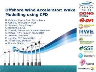
Offshore Wind Accelerator: Wake Modelling using CFD
Offshore Wind Accelerator: Wake Modelling using CFD. B. Gribben, Frazer-Nash Consultancy B. Gellatly, The Carbon Trust M. Jim énez , Dong Energy C. Balcombe, E.On N. Connell, Mainstream Renewable Power C. Pearce, RWE Npower Renewables D. Paredes, Iberdrola P. Housley, SSE Renewables

Offshore Wind Accelerator: Wake Modelling using CFD
E N D
Presentation Transcript
Offshore Wind Accelerator: Wake Modelling using CFD B. Gribben, Frazer-Nash Consultancy B. Gellatly, The Carbon Trust M. Jiménez, Dong Energy C. Balcombe, E.On N. Connell, Mainstream Renewable Power C. Pearce, RWE Npower Renewables D. Paredes, Iberdrola P. Housley, SSE Renewables M. Håkansson, Statkraft A. Knauer, Statoil
Contents • Offshore Wind Accelerator • Acknowledgements • Wake Effects Methods Presented • Selected Results for Extended Wake Effects Validation • Future Work
Offshore Wind AcceleratorObjective: Reduce cost of energy by 10% in time for Round 3 Offshore Wind Accelerator • Joint industry project involving 9 developers + Carbon Trust • £45m programme • 2/3 industry • 1/3 public • Set up in 2009, runs to 2014 • Two types of projects • Common • Discretionary 77% (36GW) of licensed capacity in UK waters
OWA focuses on five research areas to drive down costs Cost of energy CAPEX OPEX Yield Foundations Access systems Electrical systems Cable installation Cost of finance … Wake effects
Acknowledgements • The use of Rødsand II production data was facilitated by Chris Balcombe, Jeff Moffatt and Jorgen Bodin of E.ON, and is used with permission.
Offshore Wake Effects Methods • Initial validation of wake effects developments within OWA, using the ANSYS WindModeller code and the Fuga code from Risø, were presented at the EWEA Wind Resource event in June 2011. • The focus of this presentation is on the extension of this validation work. • Some representative results from validation studies will be shown.
Offshore Wake Effects Methods:Background • Existing simple parameterized models tended to underestimate the overall wake effects in large offshore wind farms. • A number of organisations have improved/are improving their wake effects methods. • In this work, we aim to improve accuracy for large offshore wind farms via improved physical modelling. • The challenge is that we have to expend considerable effort in developing and even using more advanced methods for modest accuracy gains. DES VTM Cost URANS RANS Linearised RANS Rapid Methods Complexity (Accuracy?)
Offshore Wake Effects Methods: Risø Fuga • Linearised RANS equations (momentum+continuity) • ‘Simple closure’: • Turbine rotor represented by an actuator disk • Fast, mixed-spectral solver using pre-calculated look-up tables (LUTs) • 105 times faster than conventional CFD • S.Ott: “Linearised CFD Models for Wakes”. Risoe-R-1772(EN). Risoe-DTU (2011).
Offshore Wake Effects Methods: ANSYS WindModeller • RANS equations • K-epsilon turbulence model, with modified closure coefficients • Turbine rotor represented by an actuator disk • Conventional flow solver • Best practice (notably meshing) developed within OWA • Modelling of buoyancy/thermal effects now included. • C. Montavon et al., “Offshore Wind Accelerator: Wake Modelling Using CFD”, EWEA Conference March 2011.
Validation Study:Rødsand II Met mast Rødsand II Nysted (Rødsand I) • Data were available for Rødsand II wind farm. • The layouts of Rødsand II and neighbouring Nysted are shown above. • Rødsand II contains a number of interesting features, such as long, curved rows, varied row alignments and farm-on-farm interactions. • A number of Case Studies, comparing measured and modelled turbine efficiency for individual turbines, have been carried out.
Validation Study:Rødsand II Met mast Rødsand II Nysted (Rødsand I) • When the wind is from SW, there is considerable variation in the wind speed from east to west. • Looking at a small number of wind-aligned rows, which are close together, mitigates against this variation – but is of course not perfect.
Rødsand II: Case Study 1 • Case Study 1 considers wakes along western rows. • The results presented here are for a narrow (5°) bin. • Both models perform very well when row alignment differs from wind direction by a few degrees (Row 3). Case Study 1 WS=10m/s WD=221° Turbine power for 5° bin (normalised by M4): • Notes on filtering measured data: • Wind speed: Take the power from a windward reference turbine, convert to wind speed using the power curve. • Wind direction: from the met mast at hub height. • Power: Normalised by the power from a windward reference turbine. • Quality check: Power of each turbine checked to be close to expected power based on turbine hub anemometer, or record discarded at that time (indicates turbines not operating normally). • Quality check: Requiring two consecutive time periods was analysed but found not to alter the mean results.
Rødsand II: Case Study 1 • Case Study 1 considers wakes along western rows. • The results presented here are for a narrow (5°) bin. • Both models perform very well when row alignment differs from wind direction by a few degrees (Row 3). Case Study 1 WS=10m/s WD=221° Turbine power for 5° bin (normalised by M4): • Fuga over-predicts wake effects when turbines are exactly aligned with the wind direction. • Agreement for wider bins is much better. • This is consistent with previous OWA validation. Row 3: 4° off WD Row 4: Aligned with WD NB: Alignment is different for last turbine
Rødsand II: Case Study 2 Case Study 2 • Case Study 2 considers wakes along the long, curved rows. • Windmodeller performs well for both bin sizes but slightly over-predicts power further along the row. • Uncertainties in the data due to coastal effects may be a contributing factor here. WS=10m/s WD=304° • Notes on filtering measured data: • Wind speed: Take the power from a windward reference turbine, convert to wind speed using the power curve. • Wind direction: from the met mast at hub height. • Power: Normalised by the power from a windward reference turbine. • Quality check: Power of each turbine checked to be close to expected power based on turbine hub anemometer, or record discarded at that time (indicates turbines not operating normally). • Quality check: Required two consecutive time periods, with data only taken for the latter.
Rødsand II: Case Study 2 Case Study 2 • Case Study 2 considers wakes along the long, curved rows. • Windmodeller performs well for both bin sizes but slightly over-predicts power further along the row. • Uncertainties in the data due to coastal effects may be a contributing factor here. WS=10m/s WD=304° Power of Row M turbines (normalised by K1): • Fuga agrees well for the larger bin but exaggerates peaks and troughs in power for the smaller bin. • This is consistent with the previous validation work. • Risø have considered this issue in recent updates to Fuga, validation of which is ongoing within OWA. 5° direction bin 30° direction bin
Rødsand II: Case Study 3 Case Study 3 WD=98° • Case Study 3 considers the impact of Nysted wakes on the eastern-most turbines of Rødsand II. • The separation distance is approximately 40 rotor diameters. • The results presented here are for a narrow (5°) bin. Power of Row 18 turbines (normalised by M18): • Notes on filtering measured data: • Wind speed: Take the power from a windward reference turbine, convert to wind speed using the power curve. • Wind direction: The yaw position of two windward reference turbines (where they agree) • Power: Normalised by the power from a windward reference turbine. • Quality check: Power of each turbine checked to be close to expected power based on turbine hub anemometer, or record discarded at that time (indicates turbines not operating normally). • Quality check: Requiring consecutive time periods results in no data. So results focus on column 18.
Rødsand II: Case Study 3 Case Study 3 WD=98° • Case Study 3 considers the impact of Nysted wakes on the eastern-most turbines of Rødsand II. • The separation distance is approximately 40 rotor diameters. • The results presented here are for a 10° bin. Power of Row 18 turbines (normalised by M18): • This is the first inter-farm validation done by OWA. • The predictive performance of both tools is encouraging. • NB: Fuga v1.4 does not support multiple turbine types • This gives an over-prediction of wake losses in this case study. WS=7m/s WS=10m/s
On-going Model Development • Development of both models has been supported by OWA Stage II funding. • This work will allow effects including atmospheric stability and wake meandering to be accounted for in the modelling, as well as delivering flexibility improvements (e.g. multiple turbine types in Fuga). • Updated versions are the subject of on-going evaluation and validation. • Some results from initial OWA validation of surface layer stability modelling within Windmodeller, based on Rødsand II wind farm, are presented here.
Surface Stability:Rødsand II Case Study 2 Case Study 2 • Data for Case Study 2 have been broken into stable, near-neutral and unstable surface layer bins. • The wind direction bin size is 30°. • Results are encouraging, with Windmodeller generally showing the right magnitude of effect. • Stable cases appear to be the most challenging. WS=10m/s WD=304° Power of Row M turbines (normalised by K1): Stable Surface Layer 0.5°C < TAir63m-TWater Neutral Surface Layer -1.5°C < TAir63m-TWater < 0.5°C Unstable Surface Layer TAir63m-TWater < -1.5°C
Conclusions – ANSYS CFD • Simple actuator disk model and associated framework based on ANSYS CFD • WindModeller • Good validation results have now been achieved for a wide range of scenarios: • Narrow and wide direction bins • Rows aligned / not aligned with the wind direction • Curved rows • Inter-farm interactions • Atmospheric surface layer stability implementation showing encouraging initial results.
Conclusions - Fuga • Novel linearised approach • Aim was to include a relatively full representation of wind farm aerodynamics, whilst maintaining the computational resource requirements of rapid empirical methods. • This validation work has extended the existing validation for Fuga to cover a more complex layout with varied row alignments, curved rows and inter-farm interactions • Results are very encouraging and suggest that the novel linearization approach can be used with confidence on both regular and non-regular arrays. • Further evidence has been found showing that a large bin size must be used to get good agreement between the model and measured data.
Future Work Future activities in the OWA Wake Effects project focus on: • Challenging the implicit assumption that atmospheric conditions are invariant from site to site – introducing new models with a new dimension to the probability distribution function; • Understanding the lack of agreement at small bin sizes, and providing improved models; • Gathering and generating wake effects validation data to extend confidence in new model developments.
Abbreviations • RANS: Reynolds-Averaged Navier-Stokes • URANS: Unsteady RANS • DES: Detached Eddy Simulation • VTM: Vortex Transport Method