Synchronous Motors
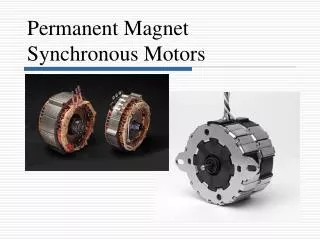
Synchronous Motors. Constant-speed machine Propulsion for SS “Queen Elizabeth II” 44 MW 10 kV 60 Hz 50 pole 144 r/min. Synchronous Motors (continued). Construction Stator identical to that of a three-phase induction motor – now called the “armature”

Synchronous Motors
E N D
Presentation Transcript
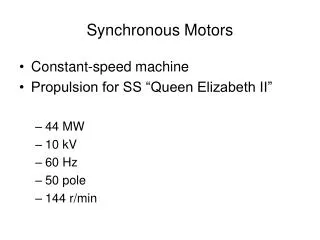
Synchronous Motors • Constant-speed machine • Propulsion for SS “Queen Elizabeth II” • 44 MW • 10 kV • 60 Hz • 50 pole • 144 r/min
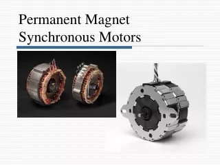
Synchronous Motors (continued) • Construction • Stator identical to that of a three-phase induction motor – now called the “armature” • Energize from a three-phase supply and develop the rotating magnetic field • Rotor has a DC voltage applied (excitation)
Synchronous Motors (continued) • Operation • Magnetic field of the rotor “locks” with the rotating magnetic field – rotor turns at synchronous speed
Cylindrical (Round) Rotor Constructed from solid steel forging to withstand large centrifugal stresses inherent in high-speed operation Used for high speed, low inertia loads (low starting torque)
Salient-Pole Rotor Excitation Windings
Salient-Pole Rotor with shaft-mounted DC exciter Need carbon brushes to make contact with the commutator
Synchronous Motor Starting • Get motor to maximum speed (usually with no load) • Energize the rotor with a DC voltage
The VARISTOR or resistor in shunt with the field winding prevents high voltage from being induced during locked-rotor and acceleration. The induced current helps to accelerate the rotor by providing additional torque.
How it works • Frequency-sensitive Control circuit • Looks at emf induced in the field • fr = sfs • At locked-rotor, s=1, fr = fs • Open SCR1 – block current from field • Close SCR2 – connect discharge resistor across the field
How it works (continued) • As the speed approaches ns, fr gets small, fr = sfs approaches 0 • Open SCR2 – disconnects the discharge resistor • Close SCR1 – allows field current to flow
Salient-Pole Motor operating at both no-load and loaded conditions Angle δ is the power angle, load angle, or torque angle
Rotating Field Flux and Counter-emf • Rotating field flux f due to DC current in the rotor. A “speed” voltage, “counter-emf”, or “excitation” voltage Ef is generated and acts in opposition to the applied voltage. • Ef = nsfkf
Armature-Reaction Voltage • Rotating armature flux, ar is caused by the three-phase stator currents. The induced speed voltage caused by the flux ar cutting the stator conductors. • Ear = nsarka
Armature-Reaction Voltage (continued) • Ear = nsarka • ar proportional to armature current Ia • Ear = (Ia)(jXar) • where Xar = armature reactance (Ω/phase)
Equivalent Circuit of a Synchronous Motor Armature (One Phase)
Phasor Diagram for one phase of a Synchronous Motor Armature
Synchronous-Motor Power Equation • In most cases, the armature resistance is much smaller than the synchronous reactance, so the synchronous impedance Zs is approximately equal to jXs .
The Equivalent-Circuit and Phasor Diagram IaXscosθi = -Efsinδ
The Synchronous-Motor Power Equation • VTIacosθi = -(VTEf/Xs)sinδ • VTIacosθi = power input per phase = Pin,1Φ • -(VTEf/Xs)sinδ = magnet power per phase developed by a cylindrical-rotor motor (a function of Ef and δ) • Pin,1Φ = -(VTEf/Xs)sinδ is the synchronous- machine power equation • For three phases, • Pin = 3(VTIacosθi) proportional to Iacos θi • Pin = 3(-VTEf/Xs)sinδ proportional to Efsinδ