Download
1 / 55
550 likes | 720 Vues
Cumulative Radiated Emissions From Metallic Broadband Data Distribution Systems. Dr I D Flintoft Dr A D Papatsoris Dr D Welsh Prof A C Marvin York EMC Services Ltd. University of York. Scope. ionosphere. Sky Wave. 3-30 MHz. Space Wave. 0.1-30 MHz. Ground Wave. 0.1-3 MHz. London.

E N D
Cumulative Radiated Emissions From Metallic Broadband Data Distribution Systems Dr I D Flintoft Dr A D Papatsoris Dr D Welsh Prof A C Marvin York EMC Services Ltd. University of York
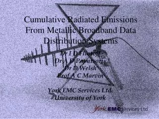
Scope ionosphere Sky Wave 3-30 MHz Space Wave 0.1-30 MHz Ground Wave 0.1-3 MHz London Rome Near Field suburban rural average UK ground 0 km 5 km 200 km 1500 km
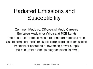
Contents • Overview of PLT and xDSL technologies • Modelling methodology • RF launch models and measurements • Sky wave propagation of PLT & VDSL • Ground wave propagation of ADSL &VDSL • Spectrum management • Conclusions
Spectrum and Technologies 30 kHz 300 kHz 3 MHz 30 MHz Low Frequency (LF) Medium Frequency (MF) High Frequency (HF) Ground Wave Sky Wave Space Wave ADSL (25 kHz-1.1 MHz) VDSL (1.1-30 MHz) DPL (2.9 & 5.1 MHz)
Power Line Telecommunication (PLT) • Propriety systems • PowerNET: 9-95 kHz (EN50065) • Digital Power Line (DPL) • Frequencies: 2.2-3.5 & 4.2-5.8 MHz • 2 Mbit/s channels demonstrated • Uses low voltage (LV) network
Mains Network Topology DPL Cell = Data Terminal Medium Voltage (MV) Network Low Voltage (LV) Network Secondary Substation Transformer 50 single phase services off each distributor Primary Substation Transformer To High Voltage (HV) Network 250 m
CU Physical Structure Of LV Network Armoured Cable • Underground and overhead distribution • Armoured cable • Conditioning units (CU) may be used Conditioning Unit (CU) LV network Network internal mains network MV network CU LV network substation data port data network
Input Power For A DPL Cell • DPL cell – coherently excited segment of network • Physical channel shared by all users in cell • Multi-user access scheme: TDMA • Power spectral density from terminal = –40 dBm/Hz = 1 mW in 10 kHz bandwidth • 10 kHz = typical HF AM radio bandwidth
Digital Subscriber Line (xDSL) • Overlay technology enabling broadband services on telephony metallic local loop • Symmetric and asymmetric upstream/downstream data rates • Data rates up to 50 Mbit/s (VDSL) • CAP, QAM, DMT modulation techniques
Telecommunications Network overhead distribution overhead drop MDF underground distribution cross connect cross connect 50 m 1.5 km footway junction box exchange 4 km 300 m = Data Terminal underground drop
xDSL Varieties FTTEx = Fibre To The Exchange, FTTCab = Fibre To The Cabinet
Physical Structure Balance of UTP • Bundles of unshielded twisted pair (UTP) • Designed for POTS – up to a few kHz • Cable balance – degrades with frequency • Network balance – interfaces • Splitters • Three wire internal cabling (New cable under controlled conditions)
Modelling Methodology • Identify coherently excited network elements • Determine the radiative characteristics of these network elements • Construct an effective single source for cumulative emissions – pattern & power • Use these effective sources in propagation calculations
RF Launch Models • Numerical Electromagnetics Code • Sommerfeld-Norton lossy ground model • Common-mode current model • Predict antenna gain and radiation efficiency of the network elements • Underground cables not considered these will be conservative estimates
Network Elements PLT House Main Ring Street Lamp 10 m 3N m xDSL 6 m Overhead Drop (Splitter) Overhead Drop (No Splitter) N Storey Building (N=1,2,…, 10)
Antenna Patterns For xDSL • At low frequencies (ADSL) patterns are omni-directional • Model using an effective short vertical monopole Normalised gains at 1 MHz
Validation Measurements • Measurements on UTP aerial drop cable • Balanced and unbalanced connections • Results used to calibrate the NEC launch models
Cumulative Radiated Power • Digital data transmission is a random process which can be modelled as a noise source • Cumulative field from incoherently excited network elements calculated by noise power addition (REC. ITU-R PI.372-6) • Phase effects ignored
Sky Wave Propagation • Time of day • Time of year • Transmitter antenna power • Transmitter antenna pattern • Transmitter antenna position • We have considered transmission on a February evening
ITS (Institute For Telecommunication Sciences) HF Propagation Software • Package caters for area coverage or point to point predictions • Allows choice of several propagation models: ICEPAC, VOACAP, REC533 • We chose to use REC533 model based on advice from RAL and the ITU • Launch power and antenna pattern
DPL Source Power For London • Power in 10 kHz bandwidth: 1 mW • Area: 2500 km2 • Size of DPL cell: 0.28 km2 (diameter 600 m) • Total number of cell: 2500/0.28 8925 • Total input power: 8925 1 mW = 8.9 W 40 dBm • Antenna gain: –15 dB • Total radiated power: 40 – 15 = 25 dBm
Coverage Of London At 5.1 MHz 0 Subtract 15 dB to read true dBmV/m, .i.e. for 15 dBmV/m read 0 dBmV/m London cumulative antenna Isotropic antenna
Cumulative DPL Sky Wave From Many Urban Areas • Since the coverage from each urban area is Europe wide we need to sum the field from many urban areas • Major sources over UK would be the Ruhr area of Germany, London, Birmingham and Manchester • Total field over UK due to these major sources plus other major UK cities is predicted to be between 5 and 11 dBV/m • Established ITU noise floor is 8 dBmV/m (rural area)
VDSL Source Power For London • Drop model without internal cables • Average of 1000 homes per km2 • 25 % technology penetration • Antenna gain of –25 dB (corresponds to 20 dB cable balance parameter) • Terminal input power –60 dBm/Hz or –20 dBm/10kHz • Total radiated power 13 dBm (20 mW)
Coverage Of London At 8 MHz Subtract 27 dB to read true dBmV/m, .i.e. for 15 dBmV/m read -12 dBmV/m
Cumulative VDSL Sky Wave From Many Urban Areas • Sum powers from major UK cities and Ruhr area of Germany • Cumulative field over UK at 8 MHz is –6 dBmV/m in 10 kHz bandwidth • Established ITU noise floor is 8 dBmV/m (rural area) • 10 dB lower than DPL
Groundwave Propagation Theory (1) • Sommerfeld (1909), Norton (1936, 1937) • (V) fields >> (H) fields • A(d,f,,) for (V) polarised fields • Attenuation factor calculated according to ITU-R P.368, originally developed by GEC
Groundwave Propagation Theory (2) • The E-field formula applies to a linear short (h<<) radiative element • NEC used to determine the equivalent FMPt of radiative structures associated with xDSL • Calculations done for upstream and downstream mode of transmission • Radiation patterns omnidirectional for ADSL • Balance, attenuation of UTPs
Calculation strategy of cumulative emissions (1) • Electric fields Ei from uncorrelated individual sources add incoherently, i.e., • A: area enclosing all radiating sources in m2 • pi: percentage of building type associated with ith radiating source • Di: density of installations per unit area • Mpi: fraction of market penetration • Li: fraction of installed lines used concurrently
Calculation strategy of cumulative emissions (2) • Step 1. Definition of radiating medium, A=25km2 • The RSS summation, lends itself to an active spreadsheet implementation
Calculation strategy of cumulative emissions (3) • Step 2. Definition of makeup of city buildings
Calculation strategy of cumulative emissions (4) • Step 3. Specify reference radiating efficiencies, balance and attenuation at frequencies of interest for upstream and downstream transmission
Calculation strategy of cumulative emissions (5) • Step 4. Define the appropriate transmission spectral mask, i.e., for ADSL PSD=-34.5dBm/Hz (upstream 138-276 kHz), PSD=-36.5dBm/Hz (downstream 138-1104 kHz). • Step 5. Calculate the unattenuated electric field for each radiative element, i.e.,
Calculation strategy of cumulative emissions (6) • Step 6. Calculate the appropriate electric field correction factor for each radiative element. • Step 7. Evaluate the total electric field by performing the RSS summation over all xDSL installations.
Test cases and results ADSL(1) • Case 1. A=25 km2, bal=40dB, Mpi=20%, Lui=10%
Test cases and results ADSL(2) • Case 2. A=25 km2, bal=30dB, Mpi=50%, Lui=10%
Balance Radiation levels increase by a margin equal to the balance difference in dB. E(bal2)=E(bal1)+bal, bal= bal1 - bal2 Market Penetration E(M2)=E(M1)+M, M=10log(M2/M1) Distance -20 dB/decade for f(100kHz - 400kHz) -25 dB/decade for f(600kHz - 800kHz) -30 dB/decade for f(1000kHz) Test cases and results ADSL(3)
Summary of results for ADSL • Emission electric fields resulting from cumulative ATU-R upstream and MDF downstream transmissions at distance 1km away from the effective emission centre.(M=20%, L=10%, Typical bal=30 dB)
Graph of current noise floor, ITU-R P.372 • Median noise electric field at a receiver with bandwidth 10kHz at 12 noon in a residential location in the central UK.
ADSL and current noise floor • No likely change to the established median electric noise field for the well balanced city (bal=50 dB) model at d>1km away from the MDF centre. • For the typically balanced city model ADSL fields are predicted above the current noise floor (cnf) • ATU-R field > cnf by 5dB - 10dB at d<2km • MDF field > cnf by 10dB - 20dB at d<3km • For distances > 10km, ADSL<cnf
Summary of results for VDSL • Emission electric fields resulting from cumulative NT-LT upstream and LT-NT downstream transmissions at distance 1 km away from the effective emission centre. (M=20%, L=20%, Typical bal=20 dB.)
VDSL and current noise floor • No likely change to the median electric noise field for the well balanced small city (bal=30 dB) model at d>1km away from the emission centre. • For the typically balanced city model VDSL fields are predicted above the current noise floor (cnf): • NT-LT field > cnf by 10dB - 20dB at d<1.5km • LT-NT field > cnf by 5dB - 15dB at d<1.5km • For distances > 5km, VDSL<cnf. • Radiation diagrams of radiative elements give rise to significant space wave component.
Spectrum management issues • AM broadcasting in band 6 (MF) • For ‘good’ quality reception • 88dBV/m, 74dBV/m, 60dBV/m for typical city/industrial, city/residential and rural/residential areas, respectively. • AM transmitter serving designated metropolitan area enclosed by a 50km radius in UK. • =15, =10mS/m, Pt=10kW • PR=30dB, thus interfering field 44dBV/m • xDSL(d>1km)< 44dBV/m, but Gaussian in nature • For rural locations near xDSL fields important
Spectrum management issues • Digital MF broadcasting • DRM consortium preliminary specification • Narrow bandwidth (max 10kHz), thus: • very efficient source coding scheme [MPEG-4 AAC] • multi-carrier modulation to overcome multipath, Doppler, [OFDM] • high state linecode modulation scheme, [QPSQ, 16QAM, 64QAM depending on service requirements] • Protection ratios: • AM interfered with by DM, [f/kHz=0, PR=36dB] • DM interfered with by AM, [f/kHz=0, PR=0dB] • DM interfered with by DM, [f/kHz=0, PR=15dB]
Spectrum management issues • Digital MF broadcasting • DRM consortium preliminary specification • Carrier-to-noise ratios: • C/N of 24dB for BER=1x10⁻⁵ is at least required.
Spectrum management issues • Power savings of 4-8dB can be made by DM transmitters, for same daytime coverage. • xDSL(d<1km)>C/N, near xDSL ? • assessment of xDSL mux and mod techniques
Spectrum management issues • AM transmitters to be phased out by 2020 • Lower PR could be used, 10-15 dB less than the currently assumed for AM, thus: • reduced radiation of digital transmitter power • much quieter EM environment • If xDSL>planned interference value: • DM power must increase (financial implications?) • concerted actions of broadcasting authorities to restore the service • xDSL near fields at remote locations?


![Cumulative distribution [%]](https://cdn1.slideserve.com/2142714/slide1-dt.jpg)