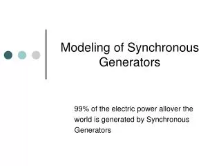
SYNCHRONOUS GENERATORS
SYNCHRONOUS GENERATORS. SUBMITTED BY: Ms. JASPREET KAUR ASST. PROFESSOR-EEE. SYNCHRONOUS GENERATORS Phasor Diagram of Equivalent Circuit. Voltages in Syn. Gen. are ac & expressed in phasor which have both magnitude and angle , therefore need to be presented in 2 dimensional plot.


SYNCHRONOUS GENERATORS
E N D
Presentation Transcript
SYNCHRONOUS GENERATORS SUBMITTED BY: Ms. JASPREET KAUR ASST. PROFESSOR-EEE
SYNCHRONOUS GENERATORS Phasor Diagram of Equivalent Circuit • Voltages in Syn. Gen. are ac& expressed in phasor which have both magnitude and angle, therefore need to be presented in 2 dimensional plot. • KVL relation of one phase can be plotted in terms of phasor voltages through this 2 dimensional plot namedphasor diagram • which show the relationship between different voltages and currents
SYNCHRONOUS GENERATORS Phasor Diagram of Equivalent Circuit • Figure below show the phasor diagram when supplying a load at unity power factor • EA differs from Vφ by resistive & inductive voltage drops, all referenced to Vφ which arbitrarily assumed at an angle of 0◦
SYNCHRONOUS GENERATORS Phasor Diagram of Equivalent Circuit • Phasor diagram when generators operating at lagging & leading power factors
SYNCHRONOUS GENERATORS Phasor Diagram of Equivalent Circuit • Note:at specific phase voltage & armature current, a larger internal voltage EA required for lagging loads than for leading loads • Therefore a larger field current required with lagging loads to get same terminal voltage EA=Kφω • Alternatively for a given IF and load current , Vφ is lower forlagging loads& higher forleading loads • In real synchronous machines, XS normally much larger than RA & often neglected in qualitative study
SYNCHRONOUS GENERATORS Power and Torque • A synchronous generator is a synchronous machine used as generator • converts mechanical energy to 3 phase electrical energy • Source of mechanical energy is prime mover (a diesel engine , a steam turbine, …) • Any source employed should have an almost constant speed regardless of load • If it were not constant, the power system frequency would wander
SYNCHRONOUS GENERATORS Power and Torque • Not all mechanical power going to a synchronous generator becomes electrical powerthe difference between input & output power represent losses, Power flow Diagram
SYNCHRONOUS GENERATORS Power and Torque • input mechanical power is shaft power in generator • Pin=Тprime-moverωm (Тprime-mover ≡ Tapp in text book) • Pconv=Tgenerated ωm = 3EAIA cos γ (γ angle between EA and IA) (Tgenerated ≡Tind in text book) • Difference betweenPinandPconv in generator represents mechanical, core, and stray losses of machine
SYNCHRONOUS GENERATORS Power and Torque • Real elect. output power of syn. Gen. in line quantities: Pout=√3 VT IL cosθ in phase quantities: Pout=3 Vφ IA cosθ reactive power output: Qout=√3 VT IL sinθ Qout=√3 Vφ IA sinθ ignoring armature resistance RA (XS>>RA), a useful relation can be derive to approximate output power of Gen.
SYNCHRONOUS GENERATORS Power and Torque • Generator Equivalent circuit for Δ connection
SYNCHRONOUS GENERATORS Power and Torque • To derive that useful equation, when stator resistance ignored, phasor diagram employed
SYNCHRONOUS GENERATORS Power and Torque • The vertical segment bc isEA sinδ or XS IA cosθ IA cosθ = EA sinδ / XS • Substituting this in equation of Pout P = 3Vφ EA sinδ / XS • since resistances assumed zero, losses not included in this equation (& it is both Pconv ,Pout) • Above equation shows power produced by a Syn. Gen. depends on angle δ (between Vφ,EA), the torque angle • Maximum power that Gen. can supply occurs when δ=90◦. At this angle sinδ=1 Pmax=3Vφ EA / XS (1)
SYNCHRONOUS GENERATORS Power and Torque • Maximum power in last equation called “static stability limit” of Gen. • Real or practical Gen. never get close to this limit • Full load torque angles of 15 to 20◦ are typical angle of real machines • If Vφassumed constant, real power output directly proportional to IA cosθ and EA sinδ • These are useful for plotting phasor diagram of Syn. Gen. as load changes
SYNCHRONOUS GENERATORS Power and Torque • From chapter 4, torque developed in a Gen. can be expressed as: • Тind= k BR X BS • Tind=k BR X Bnet • Magnitude of torque in this equation is: • Тind=kBRBnet Sinδ • δ: angle between rotor and net magnetic fields • Since BR produces voltage EA, and Bnet produces voltage Vφ, angle δ between EA and Vφ is same as angle between BR and Bnet
SYNCHRONOUS GENERATORS Power and Torque • Alternative expression for this torque in syn. Gen. is derived (employing Pconv= Tindωm) and Equation (1): Tind=3Vφ EA sinδ/(ωm XS)(2) • This equation gives torque in terms of circuit parameters, while the equation in last chapter expressed it in terms of magnetic quantities
SYNCHRONOUS GENERATORSMEASUREMENT of MODEL PARAMETERS • Equivalent circuit of synchronous generator contains 3 quantities that must be determined to describe behavior of a real Syn. Gen. 1- relation between field current & flux (IF & EA) 2- Synchronous reactance 3- Armature resistance • To determine these parameters, the first step is to do open-circuit test 1- Generator is turned at rated speed, and terminals disconnected from loads, field current set to zero 2- Field current gradually increased in steps, and terminal voltage measured at each step along the way
SYNCHRONOUS GENERATORSMEASUREMENT of MODEL PARAMETERS • Leave terminals open IA=0, Vφ= EA and thus construct a plot of EA or VT versus IF • This plot is open circuit characteristic (OCC) of Gen. • With this characteristic, internal generated voltage of Gen. for any given IF can be determined • typical characteristic shown
SYNCHRONOUS GENERATORSMEASUREMENT of MODEL PARAMETERS • Note : in this characteristic, as If increases first curve is almost perfectly linear until some saturation observed at high field current • Unsaturated iron in frame of synchronous machine has a reluctance several thousand times lower than air-gap reluctance at first all mmf is across air gap and resulting flux increase is linear • When iron saturate reluctance of iron increase profoundly and flux increases more slowly with a similar increase in mmf • Linear section of OCC called air-gap line
SYNCHRONOUS GENERATORSMEASUREMENT of MODEL PARAMETERS • Second step is to perform a short circuit test 1- adjust field current to zero 2- short circuit terminals of generator through a set of ammeter 3- armature current IA or line current IL measured as IF increased 4- such a plot named short circuit characteristic (SCC) • It is a straight line
SYNCHRONOUS GENERATORSMEASUREMENT of MODEL PARAMETERS • It is a straight line, since employing the equivalent circuit developed in this section: IA= EA/(RA+jXS) • Phasor diagram shown: • Flux density vectors shown:
SYNCHRONOUS GENERATORSMEASUREMENT of MODEL PARAMETERS • Bnet is very small since almost BR and BS cancels • The machine is unsaturated and SCC is linear • The magnitude of current: IA= EA / √[RA ^2+jXS ^2] • internal Impedance of machine ZS=√RA^2+XS^2=EA/IA • Since XS>>RA above relation reduces: XS≈ EA/IA =Vφ,OC/ IA (3) • if EA and IA known for given situation, synchronous reactance XS can be found
SYNCHRONOUS GENERATORSMEASUREMENT of MODEL PARAMETERS • Approximate method for determining synchronous reactance XS : 1- measure internal voltage EAopen circuit test at the specific field current (OCC) 2- measure short circuit current flow IA,SC at the same field current (SCC) 3- Find XS using the approximate equation (3)
SYNCHRONOUS GENERATORSMEASUREMENT of MODEL PARAMETERS • Concern: • the EAis determined from OCC where machine is partially saturated for large field currents • While IA is determined form SCC , where machine is unsaturated at all field currents • Therefore at high field currents (that core is saturated in OC) EA measured from OCC at a specific If≠ EA measured at same If under short-circuit conditions • This makes resulting value of XS only approximate
SYNCHRONOUS GENERATORSMEASUREMENT of MODEL PARAMETERS • However, answer found by this method is accurate up to the saturation point • So, unsaturated synchronous reactance XS,u can be found at any If in linear portion of OCC • Approximate Xs varies with degree of saturation of OCC, so it should be calculated at approximate load on machine • Plot of approximate XS as function of If shown
SYNCHRONOUS GENERATORSMEASUREMENT of MODEL PARAMETERS • It is important to know winding resistance as well as synchronous reactance • Resistance can be approximated by applying dc voltage to winding while machine is stationary & measuring the resultant current flow • use of dc voltage means reactance of windings will be zero in measurement • However, this is not perfect since ac resistance is larger than dc resistance due to skin effect • Measured value of resistance can be inserted in impedance equation to improve determination of synchronous reactance, however this doesn’t help since the error due to saturation has much larger effect in Xs