Baseband PPM and PAM Algorithm Implementation
Baseband PPM and PAM Algorithm Implementation. Kenneth Rice, Joel Simoneau, and Dr. L. Wilson Pearson. Introduction. Modulation Techniques. Pulse Amplitude Modulation:. Pulse Position Modulation:.

Baseband PPM and PAM Algorithm Implementation
E N D
Presentation Transcript
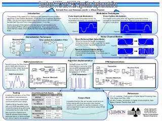
Baseband PPM and PAM Algorithm Implementation Kenneth Rice, Joel Simoneau, and Dr. L. Wilson Pearson Introduction Modulation Techniques Pulse Amplitude Modulation: Pulse Position Modulation: The purpose of this research is to implement two baseband communication algorithms: Pulse Position Modulation (PPM) and Pulse Amplitude Modulation (PAM). The two techniques implemented to demodulate PPM and PAM are the Matched Filter and Time Limited Accumulation (TLA) filter. Another purpose of this research is to test several implementations for demodulating PPM for efficiency and productivity. This is done using two noise channel models: Direct/Reflected Path Noise and Random Inversion Noise. The location of the pulse within the specified transmission frame indicates the transmitted information. Figure1B gives an example of this kind of modulation. The amplitude of the pulses denote the transmitted information. An example is shown in Figure1A. Figure1A Figure1B Noise Channel Models Demodulation Techniques Direct/Reflected Path Noise Model: Matched Filter: Time Limited Accumulation Filter: When the transmitted signal changes path during transmission in such a way that the signal becomes inverted. Figure3A is an example. Figure3A Random Inversion Noise Model: A more complicated version of the Direct/ Reflected Path Noise Model. This can be seen in Figure3B Figure2A Figure2B Figure3B Algorithm Implementation PPM Implementations: PAM Implementations: Figure4A shows the Xilinx blocks used in MATLAB’s Simulink to implement PAM. Graph1A shows the transmission of ‘001100’. Figure4B shows the PPM implementation and some of the demodulation schemes used for testing. Graph1B shows the transmission of ‘01101’. Transmitter: Transmitter: Receiver (TLA): PAM Transmission PPM Transmission Receiver (Matched): Receiver (Matched): Graph1A Figure4A Figure4B Graph1B Testing Direct/Reflected Path Results Table1A References In testing the efficiency of the PPM demodulation implementations: [1] L.C. Ludeman, Fudamentals of Digital Signal Processing. New York: Harper and Row, 1986. [2] M.B. Pursley, Introduction to Digital Communications. New Jersey: Pearson Prentice Hall, 2005. Future Work • bits were randomly transmitted and received with each design • Additive White Gaussian Noise with a 4.8 SNR was added to the transmitted signal along with being manipulated by the noise model. A possible direction that can be taken would be to do further testing with more accurate noise channel models and to quantify the relative complexity of the various algorithms to give a performance versus FPGA memory trade-off. Random Inversion Results Table1B SURE Note that N/A in Table1A and Table1B indicate that the design performed above or below average and did not need to be repeated. Summer Undergraduate Research Experience