Download
1 / 21
210 likes | 354 Vues
d.c-Sources of Polarized Electrons. Kurt Aulenbacher Institut für Kernpysik, Uni Mainz LA3Net Workshop Laser based particle sources Geneva, 21.02.2013. Polarized photocathode physics Photocathode operation Polarized sources: past and future. Outline.

E N D
d.c-Sources of Polarized Electrons Kurt Aulenbacher Institut für Kernpysik, Uni Mainz LA3Net Workshop Laser based particle sources Geneva, 21.02.2013
Polarized photocathode physics • Photocathode operation • Polarized sources: past and future Outline
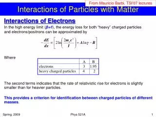
Idea: Transfer Photon helicity by s±photo-absorption from (P3/2, mj= ± 3/2) to S1/2, mj= ± 1/2 Photocathode-fundamentals • direct semiconductor with sufficient S/O splitting (GaAs) • tetragonal deformation of unit cell: limits structure size (‘bulk’) to d~0.1mm << absorbtion length (1/a >1mm) • aquivalent to deformation: periodic structure from two different materials (SUPERLATTICE) (T. Maruyama et al (1993), T. Nakanishi et al. (1993)) • Effective electron transport to surface: diffusion length L>>d • Negative Electron Affinity (NEA): high escape probability Pesc (but: Recombination on bulk/vacuum and bulk/buffer interfaces!)
Photon Electron The surface: Creator of all evil…. Photocathode: Realisation Quantum Efficiency Polarization: NOT to scale: Photocathode-Superlattice # ‘7-395’ created by Sankt Petersburg state technical university & Joffe Institute St.P. for U-Mainz
working point:Pmax,QEmax Photocathode: d.c.-Experiment L. Gerchikov et al. Proc. PESP2010 • Polarization: max ~0.85 • Try to disentangle different factors! • Mixing • Transport depolarization • Surface effects Quantum efficiency: QE ~1% at Pmax PhotoSensitivity: QE*l/1.24 [A/Watt] Corresponds to ~6mA/Watt
Emission behavior of active structures with d~0.1mm is mixed between diffusive and ballistic and ttrans/tspin~0.02 K.A. et al. J. Appl. Phys. 92, 7536 (2002) Superlattices: High P, high QE, High speed L. Gerchikov et al. Proc. PESP2010 ~0.93-0.98 (from energy resolved measurements) ~0.95 (theory) ~0.97-0.98 (this measurement)
NEA GaAs: high brillance I Bazarov et al. Proceedings PAC 07 NEA GaAs operated at Bandgap offers reasonable Sensitivity ~5mA/Watt + high brightness. ……. BUT: Operational stability issues!
NEA surfaceisgeneratedbydipolelayer • FormedbyCesiumandoxygen. • NEA GaAsoperationisdependend • On integretyofthislayerwhichis • Constantlyjeopardizedbyinteraction • with (hostile!) environment Operational stability Double dipole model: C.Y. Su, W.E. Spicer et al. J. Appl. Phys. 54, (1983)
Operational Stability: Observed time constant Parallel acting deteriorating processes • Vacuum-lifetime • 1000 h requirespressure • of oxidizing Molecules, • e.g. H2O, <10-13 mbar • Field emission (equivalent • to „Loss“): ruleofthumb: • 1000 hoursreq. <10nA. • Why? K.A. Habilitation thesis, 2007 Proceedings of the 17th International Spin Physics Symposium. AIP Conference Proceedings, Volume 915, pp. 1019-1024 (2007);
Operational Stability: Observed time constant Parallel acting deteriorating processes • Demonstration of beam loss • effect: 5 mA lost at 1 m distance • in beamlinebeforephotocathode • Absolute beam lossesclose • tothecathode must bekept • below 10nA forgoodlifetime R. Barday et al. Proceedings of the 17th International Spin Physics Symposium. AIP Conference Proceedings, Volume 915, pp. 1019-1024 (2007);
Further Stability issue: IBB …..Ions resulting from electron impact on gas atoms move backward (Ion back bombardment) Electrons move forward… IBB limits the lifetime „locally“ K.A. et al. NIM A 391 (1997)
Vacuum, Fieldemission • Vacuum/field emission experiment with “MAMI upgrade” source • Lifetime with HV 100kV on, valves open: 26-50 days (negligible current.)
Mask activation • Transmission losses on first 2m beamline ~10-3 • max current <10mA for 100 hour lifetime • losses 10-6 (if mask activated) • Max current 10mA ??? no, because of IBB effect! Ins. tube I Electron beam out Mask activation
IBB-Effect @2.5mA (Igor Alexander, Proceedings PESP2010) Under mask activation conditions we find that at currents <100mA operational stability at MAMI (typical c.w. acc. with external beam) is limited by vacuum lifetime; NOT by current
d.c. –sources past and future • Todays „standard“ design invented by SLAC ~1975 • Improvements since : load-locks, NEG arrays, mask activation, hydrogen cleaning, synchro-lasers, Source with load lock& prep chamber NEG array SLAC source
Charge & fluence lifetime Ionization E (El. Field) In the “absence of other effects”, photocathode lifetime is limited due to ion backbombardment (IBB) IE (Electron current) Area (A) We can observe the ‘charge lifetime’ (in Coulombs) Interesting for ‘high av. brightness’ application is the ‘fluence lifetime’ (in Coulombs/cm2): now compare present situation and future demands…
ERL-EIC feasible with ‘state of the art’ if area scaling holds Cooler and light source require either better vacuum regime, higher gradient or more robust photocathode (*) Assumption: t=30days (1 month continuous operation)
Is area scaling violated? J. Grames et al. Phys Rev. STAB 14 (043501) (2011) • Note: Increasingspottimesfiveincreaseschargelifetime • *25, observed: ~*6 • Very difficult to exclude transmission loss & geometry effects
Modern source designs: inverted gun J. Grames et al. Phys Rev. STAB 14 (043501) (2011) Advantages: more compact, less insulator and electrode area
Future source designs: Gatling gun d.c. dipoles for 20 trajectories 700 kHz rotating Dipole/quadrupole field I Ben-Zvi et al. BNL „Gatling“ source for eRHIC collider: 20 Photocathodes, 14 MHz Bunchrepetition rate, 3nC/bunch (40mA) 2mA/cathode Highly polarized beam .
Summary • NEA superlattice photcathodes offer high spin-polarization ~90% • In principle they have most of the desirable properties • for unpolarized photoinjectors too: • high brillance, fast response • BUT: extreme sensitivity makes application usually unattractive • (if spin polarization is not mandatory!) • After sevarel decades of c´technical improvements, all exisitng • machines can be supplied reliably • Future machines (eRHIC, LHeC): demanding, but probably • feasible • Making use of NEA cathodes for ERL based light sources • (100mA current) requires considerable progress with the IBB • problem (=residual gas density) cryogenic environment • and/or SRF-source a la Rossendorf?