Lab 4: UART
Lab 4: UART. Administrations. Week 10 (4/20): Term project check point #1 Make your robot car move Forward, backward, turn left, turn right Avoid Obstacles. UART. UART: Universal Asynchronous Receiver Transmitter Two wires: Rx, Tx Full duplex Asynchronous No common clock required

Lab 4: UART
E N D
Presentation Transcript
Administrations • Week 10 (4/20): Term project check point #1 • Make your robot car move • Forward, backward, turn left, turn right • Avoid Obstacles
UART • UART: Universal Asynchronous Receiver Transmitter • Two wires: Rx, Tx • Full duplex • Asynchronous • No common clock required • Without common clock • How do they communicate?? A Rx Tx B Tx Rx
Universal data rates • Two devices agree on same data rate • Baudrate: 1200, 2400, 4800, 9600, …, (bits per second) A (1 MHz system clock) B (8 MHz system clock) 9600 9600 Baudrate generator Baudrate generator UART UART Baudrate: 9600 bps Length of a bit = 1/9600 (seconds)
UART Data This bit became parity bit when parity checking is enabled • Send one character at a time • Data • One start bit • Pull-down the line • 7 or 8 bits data • One or two stop bit • Pull-up the line for one or two slots • Simple error checking: parity (optional) • Even parity: If the data has odd number of 1, parity bit = 1 (make it even); else parity bit = 0 • Odd parity: If the data has even number of 1, parity bit = 1 (make it odd); else parity bit = 0 • Four parametersfor UART communication • Baudrate, data-bit, parity, stop-bit • We wrote: 9600 8N1, • Means: baudrate=9600, 8-bit data, no parity, 1 stop bit
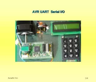
Applications All you need to do is properly configure UART for both sides (baudrate, data-bit, parity, stop-bit), and start sending/receiving data Other Sensors PC or other systems COM PORT RS232 IC Today’s Labs MSP430 USB UART USB serial IC (FT232) Other systems RS485 IC RS485 IC
UART Modules On MSP430 • Two UART modules on MSP430F1611 • USART0 and USART1 • USART • Universal Synchronous/Asynchronous Receive Transmit • The USART0 module support 3 protocols • UART • SPI • I2C • The USART1 module support 2 protocols • UART • SPI • Two protocols cannot operate simultaneously on one module
UART Modules On MSP430 There are multiplexed with digital I/O pins, remember to set the PxSEL register properly SPI pins UART pins I2C pins
USART Connections On Taroko Taroko MSP430F1611 FT232 USB serial IC PC USART1 USART0 UART I2C SPI Expansion Connector (U2) CC2420 Radio IC Taroko Schematic The UART pins and I2C pins are connected to the expansion connector, so you can connect external sensors through UART or I2C interface on USART0 module Taroko use SPI on USART0 module to control the radio IC. • The USART0 module is shared • If you connected an external sensor through UART/I2C interface • When you are using radio, you cannot read sensor • When you are reading sensor, you cannot use radio
UART Mode • Two devices • Three or more devices (multiprocessor format) • Character Format A Rx Tx B Tx Rx Seldom use, we wouldn’t talk about it A Rx Tx B Tx Rx C Tx Rx For multiprocessor format, not use Usually we use 8-bit data
UART Receive and Transmit When all the bits are collected, the received character will be written to a buffer register (UxRXBUF) and issues an interrupt. When the module detects a valid start bit, it will start collect the rest of the bits Set URXEx= 1 to enable the receiver • Receive • Transmit • To transmit another byte. You MUST wait until the previous data has transmitted. • If it is ready to transmit • A flag UTXIFGx will set to 1 • Two ways to detect • An Interrupt • A while loop to check the flag When data is written to the transmit buffer (UxTXBUF), a transmission start Set UTXEx= 1 to enable the transmitter
Baud Rate Generation UART clock source frequency must larger than (3*baud rate)! • The divider setting controlled by three 8-bit registers • UxBR0, UxBR1, and UxMCTL • The equation • UxBR = (UxBR1 << 8) + UxBR0 • Total bits • 1 start, 8 data, 1 parity, 1 stop • 11 bits in total (n = 11) DCO (SMCLK) Divider UART Clock Source Desire baud rate 32768 Hz (ACLK) • For Example: • UART Clock Source = 32768 • Desire baud rate = 2400 • Divider = 32768/2400 = 13.653 • UxBR = 13, = 0.653 Integer part Fractional part
Modulations • UxMCTL determine the fractional part • You know the summation of mi should be 7 • But what is the right combination • For Example: • UART Clock Source = 32768 • Desire baud rate = 2400 • Divider = 32768/2400 = 13.653 • UxBR = 13, = 0.653 Bit 0 Bit 7 UxMCTL m0 m1 m2 m3 m4 m5 m6 m7 m8 m9 m10
Determining the UxMCTL • Individual bit error • Baud rate, BRCLK, and UxBR are known • Choose a combination of m0 … m7 • For each bit, calculate the bit error • Find the maximum bit error among all the bits • This is the bit error of this combination • Choose another combination and calculate again • Select the combination that has minimum bit error Bit 0 Bit 7 m0 m1 m2 m3 m4 m5 m6 m7 m8 m9 m10
Example Bit 0 Bit 7 Bit 0 Bit 7 • Useful resource!!! • http://mspgcc.sourceforge.net/baudrate.html m0 m1 m2 m3 m4 m5 m6 m7 m0 m1 m2 m3 m4 m5 m6 m7 m8 m9 m10 m8 m9 m10
UART Interrupts • Two interrupt vectors • Transmission interrupt vector • Reception interrupt vector • Transmission interrupt • When UxTXBUF (transmit buffer) is ready to accept another character (previous transmission is complete) • An interrupt request is generated • UTXIFGx interrupt flag is set • The interrupt request is clear automatically when • The request is serviced • Or, a character is written to UxTXBUF • Reception interrupt • When a character is received • An interrupt request is generated • URXIFGx interrupt flag is set • The interrupt request is clear automatically when • The request is serviced • Or, UxRXBUF is read
Wait For Transmission • To transmit another byte. You MUST wait until the previous data has transmitted • Two ways to do • By a while loop • No matter you enable or disable the transmit interrupt, the UTXIFGx will set to 1 when it is ready to transmit another byte • Use a while loop to check the flag • While(!(IFG1 & UTXIFG0) • Transmit next byte after the while loop By Interrupt Enable transmit interrupt When it is ready to transmit another byte, it will generate an interrupt request Transmit next byte in the ISR Program will branch to the ISR, need extra CPU cycles Could possibly hang in the while loop
UxCTL You MUST held UART logic in reset state when you setting the UART registers
UxTCTL Select clock source If you want to disable the transmitter, wait until this bit is set to 1
Other Registers • Baud rate control registers • UxBR0, UxBR1, and UxMCTL • Receive and transmit buffer • UxRXBUF and UxTXBUF • Module enable registers • Enable/disable transmitter and receiver For UART0 For UART1
Interrupt Registers • Interrupt enable registers • Interrupt flag registers For UART0 For UART1 For UART0 For UART1
Initialization/Re-configuration UART • There are specific process flow to follow • Set SWRST • Initialize all UART registers when SWRST=1 • Enable UART module (ME1 or ME2) • Clear SWRST (SWRST=0) • Enable interrupts (optional) • Failure to follow this process may result in unpredictable USART behavior
Problems With Clock Source • To generate appropriate baud rate, you must know the frequency of UART clock source • Two clock source avaible • ACLK = 32768 Hz • SMCLK = DCO (frequency??) • UART clock source frequency must larger than (3*baud rate)! • For 32768 clock source, max baud rate is 10922 (9600) • Problems • What if you need faster baud rate • Error increase when baud rate is close to clock rate • We need faster clock source
Set DCO • We talk about how to adjust DCO frequency in lab 2 • But it is not very accurate • We can use a more accurate clock to set the frequency of DCO precisely • Use timer capture mode • Latch the current timer counter value into TxCCRx register • Use an accurate clock as a capture source • Use DCO as timer clock source Example: Timer clock source = DCO Capture source = ACLK/4 = 32768/4 = 4096 Hz If Capture_1 = 3000 Capture_2 = 3250 Freq. of DCO = (3250 – 3000) * 4096 = 1024000 Hz You can adjust the DCO by setting the registers until you get the desire frequency you want When a capture occurred, the value of timer counter is copy to the TxCCRx register Capture_1 Capture at every raising edge Capture_1 Capture source Timer Clock source You know the frequency of capture source. frequency of timer clock source = (Capture_2 – Capture_1) * Freq. of capture sourcev Counter increase at every raising edge
Today’s Labs • Lab 1: Set DCO • You don’t have to write the routine by yourself, use the sample code on course webpage (sample code form TI) • The routine sets the ACLK to 32768/4 = 4096 Hz • It use a variable “DELTA” to set the frequency of DCO • DON’T set the DCO frequency > 8 MHz • Use program in previous lab • See the LED flashed at a certain rate • If DCO = 1000000 Hz • i = 125000 • The LED should flash approximately every second • int is 16-bit long Set DCO This while loop takes exactly 8 cycles
Lab 2: Send to PC • Use the sample file on course webpage • Setting UART registers • UART setting • Baudrate = 57600, 8-bit data, no parity, 1 stop bit • Use the program in Lab 3, sense the acceleration • Send the acceleration values (x, y, z axes) to your computer • Use a terminal program (realterm) to receive the values
Lab 3: Receive From PC • From the terminal program on PC, send the following byte sequences (in Hexidecimal) to Taroko • 5A A5 53 54 41 52 54 0D 0A • 5A A5 53 4C 45 45 50 0D 0A • UART setting • Baudrate = 9600, 8-bit data, no parity, 1 stop bit • Configure your Taroko to receive these two sequence correctly
Taroko USB driver • Download Taroko USB virtual com port driver • http://www.ftdichip.com/Drivers/CDM/CDM%202.02.04.exe • Install driver • Plug Taroko to you computer’s USB port, you should see Device manager
Terminal Program • Realterm • http://realterm.sourceforge.net/ • Download Realterm program • http://sourceforge.net/project/showfiles.php?group_id=67297 • Install the program • Open the program by this way • Click Start-up -> click run • "C:\Program Files\BEL\Realterm\realterm.exe" baud=9600 port=63 Enter baud rate Enter COM port
Realterm Display format
Realterm Click here can open/close the port UART setting
Realterm Capture data to a file
Realterm Send out data