Measuring Temperature with Thermistors
Measuring Temperature with Thermistors. Academic Workshop Lab. Objective. Exploit PSoC topology to build inexpensive digital thermometer. Understand the operation of a negative temperature coefficient (NTC) thermistor.

Measuring Temperature with Thermistors
E N D
Presentation Transcript
Measuring Temperature with Thermistors Academic Workshop Lab
Objective • Exploit PSoC topology to build inexpensive digital thermometer. • Understand the operation of a negative temperature coefficient (NTC) thermistor. • Understand how to calculate Steinhart Hart constants for a specific thermistor. • Calculate temperature using the Steinhart & Hart equation. • Calculate temperature using a look up table.
Hardware Overview • CY8C3210-PSoCEval1 board. • MiniProg • Thermistor • 10k resistor • Breadboard wire
Reference Material • AN2028 Ohmmeter • AN2017 Thermistor Based Thermometer • AN2239 ADC Selection
Measuring Resistance • Unlike measuring voltage or current, measuring a a passive characteristic like resistance requires stimulus • A Classic method is to push current into a resistor and measure the developed voltage. • Only as accurate as • Current Source • ADC Gain and Offsets • Resistance limited to ADC range. • Requires different current values for wide range of resistors. • Very popular when cost of accurate current sources was less than the cost of computation.
PSoC and Measuring Resistance • For this circuit the following equation holds. • Solving for Rtest results in: • Offset errors removed by difference • Measurement offset voltages subtract out! • Gain errors removed by quotient • Measurement path errors divide out! • Accuracy determined by an external reference resistor …
PSoC and Measuring Resistance • And ADC resolution • For an n bit ADC the number of counts seen across aR is: • The reading is accurate to +/- .5 counts. • Overall resolution tolerance is: • For 14 bits and an attenuation of 15/16, the equation simplifies to:
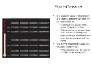
Thermistors • A negative temperature coefficient thermistor (NTC) is a semiconductor device that becomes less resistive as its temperature increases. The change in resistance is “roughly” expressed by the equation below. Where: • A is some empirical value less than one for negative temperature coefficient (NTC) thermistors. • T1 & T2 are temperatures measured in Kelvin. • R(T1) & R(T2) are the thermistor’s resistances at these temperatures.
NTC Thermistors • ”Roughly” is defined as a good approximation for an academic introduction to thermistors. • It shows the temperature/resistance relationship to be ideally exponential. • It won’t hold up for real world temperature-measuring application. • But for small temperature differences the following holds:
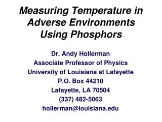
Steinhart-Hart Equation • The Steinhart-Hart equation describes the resistance change of a thermistor as related to its temperature. The equation below shows it to be a 3rd order logarithmic polynomial using three constants. Where: • A, B, and C are empirical constants. • TK & is temperature in Kelvin. • R is the thermistor’s resistance in Ohms .
Steinhart-Hart Equation • Many thermistors come with these three parameters defined. • For this particular thermistor they are in the datasheet • If not they must be calculated. • This is done by taking three points in the conversion table and solving for these constants. • It makes most sense to use the minimum, maximum, and a middle value for the temperature range for which you are interested. From the Thermistor Table Note: This is an example and not for the thermistor we are using
Steinhart-Hart Equation • Apply the three data points to the following equation. To get the three following equations. • Solve to get: A = 0.11261637e-2 B = 0.23461776e-3 C = 0.85700804e-7
Thermistors • The cost of thermistors is primarily determined by the accuracy of the thermistor’s resistance. This is where the exponential nature of thermistors works out to your advantage. • A thermistor’s resistance tolerance shows up as a temperature shift. This can be calibrated out with a single point calibration. • In test, bring the thermistor to 25˚C and measure its temperature. • Suppose it reads 26.2˚C • Software needs to store a 1.2˚offset in memory.
Thermistors • In consumer products this calibration is many times left to the user. • The user interface allows access to the temperature offset register. • The user sets this if they think the temperature is a bit low or a bit high. • A good rule of thumb is that a thermistor resistance uncertainty of n% works out to a temperature shift of approximately (n/3)˚C. This will help determine if any calibration is needed. Temperature calculations are only as accurate as the resistance measurement of the thermistor
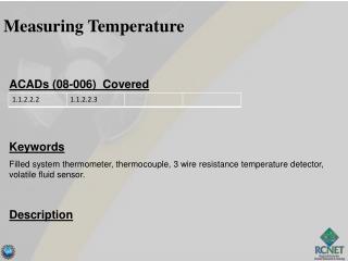
Let’s Get Started Desired Topology • Connect 10k Ohm from P05 to P01. • Connect 10k Ohm thermistor from P01 to P03. • Start Designer • Name the Project Therm. PSoC V0_Out P05 REFHI buf1 10k InputAtten V1_In P01 Buffer R ADC Therm 15R REFLO buf0 V2_Out P03
EVAL1 Connections 10K P05 Therm P03 P01 Wire
Starting a New Project • Open PSoC Designer • Select Start new project
Starting a New Project • Select Project Type • Name The Project
Starting a New Project • Select Device and Coding Method • CY8C29466-24PXI • C • OK
Select PGA UM • Select PGA and name it InputAtten • Insert into ACB00 • Set the PGA parameters to: • Atten Value set to 15/16 • Reference to AGND • Input connected to column MUX to read all three points on the resistor string
Select Second PGA UM • Select PGA and name it Buffer • Insert into ACB01 • Set the PGA parameters to: • This UM generate API in multiplex the input lines.
Select AMUX4 UM • Select an AMUX4 and rename it ADCMUX • Set its parameter has shown.
Select ADCINC UM • Select an ADCINC UM and rename it ADC. • Select a single modulator and place it in ASC10. • Select the clock to be VC2. • Place the digital block in DBB0. • Input connects to Buffer. • PWM is not used
Select LCD UM • Select and LCD UM and name it LCD. • Connect to Port 2 • BarGraph is not needed.
Rename Buffers and Pins • Connect the AnalogOutBuf_1 to P05. • Renamethis pin V0_Out. • Connect the AnalogOutBuf_0 to P03. • Rename V2_Out. • Change PO1 to be an AnalogInput. • Rename it V1_In.
(Cut and Paste from File on CD) Add Initialization Code • In the Initialization Section • Add code to start Buffer, InputAtten, ADC, and LCD. • Add code to connect REFHI to the column1analog bus. • Add code to connect REFLO to the column0 analog bus. • Declare iV0, iV1, iV2, iRvalue to be global variables. • Enable global interrupt. • Declare bTempValue to be a global 8 bit variable. • Add LookUp table.
LookUp Table Temperature Conversion • The Steinhart-Hart equation requires using the floating point math library. Floating point is slow and uses buckets more ROM compared to integer math. • An alternative is to use a look up table. For any particular thermistor, the manufacturer either supplies a R/T conversion table, or supplies the three Steinhart-Hart coefficients. If only the coefficients are supplied, a table can be generated from them. This particular thermistor has a R/T conversion table that supplied.
Create a Look Up Table • Excel file ThermTable.xls contains the 81resistance values for temperature for 0°C to 80 °C. • Calculate half values for ½°C to 79 ½°C using the following equation. • ½ degrees are used for rounding. • Add the value zero at the end.
Create a Look Up Table* • These values are used to make an ROM array WThermTable[ ] containing 81 values. *code is provided in lab file
Add Code Control Loop • In the Control Loop • Set ADCMUX to P05. • Run ADC. • Wait for data. • Place in iV0 • Set ADCMUX to P01. • Run ADC. • Wait for data • Place in iV1. • Set ADCMUX to P03. • Run ADC. • Wait for data • Place in iV2. • Calculate Resistance. • Display on LCD.
Add Code CalculateR • If iV0<-iV1 (Open Circuit) • lRvalue = -1 • Else If iV1 <= iV2 (Short Circuit) • iRvalue = 0 • Else • Calculate Resistance • Add half denominator tonumerator to implementround off.
Run • Build the Project. • Record RAM and ROM Usage. • Download to the Eval board and run. • Using the look up table determine the temperature.
Summary • PSoC makes measure resistance a cost effective option. • Temperature can easily be measure using thermistor with the Steinhart-Hart equation or look up table.