Download
1 / 19
190 likes | 204 Vues
This review discusses the status of SPARC laser and "dazzler" experiments, including the laser system layout, parameter requirements, and diagnostic systems. It also highlights the progress and timeline of the project.

E N D
SPARC Review Committee 4-10-2004 Status of the SPARC laser and “dazzler” experiments A.Ghigo for SPARC laser group
Parameter Requirement Operating Wavelength 260 nm Pulse energy on cathode 500 µJ (Q.E.=10-5) Energy jitter (in UV) 5 % rms Temporal pulse shape Uniform (20% ptp) Transverse pulse shape Uniform (20% ptp) Pulse rise time (10-90%) < 1 ps Pulse length (Gaussian) 0.5-12 ps Repetition rate 10 Hz Laser-RF jitter < 1ps rms SPARC Review Committee 4-10-2004 Spot radius on cathode Circular 1 mm Laser requested parameters
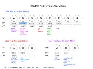
LASER SYSTEM DESCRIPTION The laser system consist of the following subsystem: a) the mode-locked Ti:Sapphire laser oscillator100 – 300 femtosecond configuration; central wavelength 800 nm with a bandwidth > 30 nm. b) the oscillator pump must be a diode pumped CW solid state laser at 532 nm (doubled Nd laser). c) the steering optics that permits to introduce the pulse shaper between the oscillator and the amplifiers d) the stretcher system composed by the optics that permit to lengthen the oscillator pulse e) the first Ti:Sapphire regenerative amplifier operating at high repetition rate (kHz) f) the pump of the regenerative amplifier must be a high power solid state laser operating in the green region (doubled Nd laser) with high repetition rate (> 1 kHz) g) the Ti:Sapphire multipass amplifier that provide the final IR energy per pulse h) the pump of the multipass amplifier must be a pulsed solid state laser (doubled Nd laser) operating at 10 Hz l) the compressor system optics that restore the laser pulse-length at the requested value m) the second and third harmonic generation crystals that convert the IR to the UV radiation. n) the synchronization system that permits to lock the timing (frequency and phase) to a stable external reference oscillator with a timing jitter less than 0.5 psec
T i : S a O s c i l l a t o r T i m e P u l s e S h a p e r Laser system schematic layout P u m p t Stretcher R e g e n e r a t i v e M u l t i p a s s Compressor a m p l i f i e r a m p l i f i e r w 3 P u m p P u m p UV Pulselength variator y G r a z i n g i n c i d e n c e C o m p e n s a t i o n x S p a t i a l F l a t t e n e r _ C u e C a t h o d e
SPARC Laser System schedule • 11/06/2003Technical Specifications ready • 27/06/2003Tender request started (delibera) • 26/11/2003Invitation letter sent to the firm • 11/02/2004Tender request closed (COHERENT) • 01/03/2004Construction started • 08/09/2004Optical table installed (Newport) • 01/10/2004Clean room tests started • 11/2004Complete system test at the factory • 12/2004Laser shipment • 2-3/2005Installation at INFN and final test
“Dazzler” experiments Shaping obtained with single passage in the AO crystal + 30 cm dispersive glass
Best results in Politecnico di Milano experiment Square Pulse at the Pulse shaper exit after the oscillator
SPARC Review Committee 4-10-2004 Brookhaven experimentDUV-FEL Laser System • Amplified Ti:Sa with 10 nm FWHM • The laser is use to drive the photocathode and to seed the HG before the undulator • The laser is composed by. • Tsunami oscillator and related pump • Regenerative and 2 multipass amplifiers • Two compressor to produce the sub-ps pulse for HGHG and 10 ps for the electron photoemission
Brookhaven experiment layout Dazzler location
SPARC Review Committee 4-10-2004 Diagnostic Systems • Laser beam time and frequency domain diagnostics: • ps streak camera for single shot low resolution measurement • UV multishot cross-correlator for high resolution (150 fs) • SPIDER for phase and amplitude reconstruction usable for pulse < 1 ps • spectrometers
SPARC Review Committee 4-10-2004 Dazzler Test • The Dazzler is used in single passage configuration before the amplifier, external dispersion is added by off-balance the stretcher-compressor • The experiment is directed toward the production of the flat top pulse after the amplification and UV-conversion.
Stretched pulse measurement The pulse is 20% flat and the edge are very sharp 350 ps Temporal profile measurements have been made only by streak camera at different position
After Pulse Compressor • Also the compressor introduce distortions. For their characterization the amplified was bypassed. The measurement after compression of the “flat” stretched pulse shows not understood changes of the shape.
17 ps After Pulse Compressor(After some work) Correction
After Pulse Amplification • Amplification seems to introduce distortions caused by gain narrowing and because the front edge experience an higher gain • Streak camera snapshot of the previous pulse after amplification upstream the compressor
Pulse shape after amplification and compression Last minute result Dazzler set up made with streak camera High resolution spectrometer needed
Next step • Use the dazzler to pre-compensate better the distortions generated by the Amplifiers and move for a fine shaping to the UV conversion
Diagnostics needed for final laser test • Two high resolution spectrometer (IR – UV) • Single shot autocorrelator • Energy meters (main laser pulse meas.) • Power meters (laser pumps meas.) • UV cross-correlator • Streak Camera
Optical transfer line status • Transfer line channel design almost ready • Optical component specs ready for call for offers • Linear stages and gimbal mounts to be defined • according to the final layout