DISTRIBUTED DBMS ARCHITECTURE
DISTRIBUTED DBMS ARCHITECTURE. DBMS STANDARDIZATION. Based on components. The components of the system are defined together with the interrelationships between components. A DBMS consists of a number of components, each of which provides some functionality. Based on functions.

DISTRIBUTED DBMS ARCHITECTURE
E N D
Presentation Transcript
DBMS STANDARDIZATION • Based on components. The components of the system are defined together with the interrelationships between components. A DBMS consists of a number of components, each of which provides some functionality. • Based on functions. The different classes of users are identified and the functions that the system will perform for each class are defined. The system specifications within this category typically specify a hierarchical structure for the user classes.
DBMS STANDARDIZATION • Based on data. The different types of data are identified, and an architectural framework is specified which defines the functional units that will realize or use data according to these different views. This approach (also referred as the datalogical approach) is claimed to be the preferable choice for standardization activities.
DBMS STANDARDIZATIONANSI / SPARC ARCHITECTURE The ANSI / SPARC architecture is claimed to be based on the data organization. It recognizes three views of data: the external view, which is that of the user, who might be a programmer; the internal view, that of the system or machine; and the conceptual view, that of the enterprise. For each of these views, an appropriate schema definition is required.
DBMS STANDARDIZATIONANSI / SPARC ARCHITECTURE • At the lowest level of the architecture is the internal view, which deals with the physical definition and organization of data. • At the other extreme is the external view, which is concerned with how users view the database. • Between these two ends is the conceptual schema, which is an abstract definition of the database. It is the „real world” view of the enterprise being modeled in the database.
DBMS STANDARDIZATIONANSI / SPARC ARCHITECTURE • The square boxes represent processing functions, whereas the hexagons are administrative roles. • The arrows indicate data, command, program, and description flow, whereas the „I”-shaped bars on them represent interfaces. • The major component that permits mapping between different data organizational views is the data dictionary / directory (depicted as a triangle), which is a meta-database. • The database administrator is responsible for defining the internal schema definition. • The enterprise administrator’s role is to prepare the conceptual schema definition. • The application administrator is responsible for preparing the external schema for applications.
ARCHITECTURAL MODELS FOR DISTRIBUTED DBMSs The systems are characterized with respect to: (1) the autonomy of the local systems, (2) their distribution, (3) their heterogeneity.
ARCHITECTURAL MODELS FOR DISTRIBUTED DBMSs - AUTONOMY Autonomy refers to the distribution of control, no data. It indicates the degree to which individual DBMSs can operate independently. Three alternatives: • tight integration • semiautonomous systems • total isolation
ARCHITECTURAL MODELS FOR DISTRIBUTED DBMSs - AUTONOMY Tight integration. A single-image of the entire database is available to any user who wants to share the information, which may reside in multiple databases. From the users’ perspective, the data is logically centralized in one database. Semiautonomous systems. The DBMSs can operate independently. Each of these DBMSs determine what parts of their own database they will make accessible to users of other DBMSs. Total isolation. The individual systems are stand-alone DBMSs, which know neither of the existence of the other DBMSs nor how to communicate with them.
ARCHITECTURAL MODELS FOR DISTRIBUTED DBMSs - DISTRIBUTION Distributions refers to the distributions of data. Of course, we are considering the physical distribution of data over multiple sites; the user sees the data as one logical pool. Two alternatives: • client / server distribution • peer-to-peer distribution (full distribution)
ARCHITECTURAL MODELS FOR DISTRIBUTED DBMSs - DISTRIBUTION Client / server distribution. The client / server distribution concentrates data management duties at servers while the clients focus on providing the application environment including the user interface. The communication duties are shared between the client machines and servers. Client / server DBMSs represent the first attempt at distributing functionality. Peer-to-peer distribution. There is no distinction of client machines versus servers. Each machine has full DBMS functionality and can communicate with other machines to execute queries and transactions.
ARCHITECTURAL MODELS FOR DISTRIBUTED DBMSs - HETEROGENEITY Heterogeneity may occur in various forms in distributed systems, ranging form hardware heterogeneity and differences in networking protocols to variations in data managers. Representing data with different modeling tools creates heterogeneity because of the inherent expressive powers and limitations of individual data models. Heterogeneity in query languages not only involves the use of completely different data access paradigms in different data models, but also covers differences in languages even when the individual systems use the same data model.
ARCHITECTURAL MODELS FOR DISTRIBUTED DBMSs - ALTERNATIVES The dimensions are identified as: A (autonomy), D (distribution) and H (heterogeneity). The alternatives along each dimension are identified by numbers as: 0, 1 or 2. A0 - tight integration D0 - no distribution A1 - semiautonomous systems D1 - client / server systems A2 - total isolation D2 - peer-to-peer systems H0 - homogeneous systems H1 - heterogeneous systems
ARCHITECTURAL MODELS FOR DISTRIBUTED DBMSs - ALTERNATIVES (A0, D0, H0) If there is no distribution or heterogeneity, the system is a set of multiple DBMSs that are logically integrated. (A0, D0, H1) If heterogeneity is introduced, one has multiple data managers that are heterogeneous but provide an integrated view to the user. (A0, D1, H0) The more interesting case is where the database is distributed even though an integrated view of the data is provided to users (client / server distribution).
ARCHITECTURAL MODELS FOR DISTRIBUTED DBMSs - ALTERNATIVES (A0, D2, H0) The same type of transparency is provided to the user in a fully distributed environment. There is no distinction among clients and servers, each site providing identical functionality. (A1, D0, H0) These are semiautonomous systems, which are commonly termed federated DBMS. The component systems in a federated environment have significant autonomy in their execution, but their participation in the federation indicate that they are willing to cooperate with other in executing user requests that access multiple databases.
ARCHITECTURAL MODELS FOR DISTRIBUTED DBMSs - ALTERNATIVES (A1, D0, H1) These are systems that introduce heterogeneity as well as autonomy, what we might call a heterogeneous federated DBMS. (A1, D1, H1) System of this type introduce distribution by pacing component systems on different machines. They may be referred to as distributed, heterogeneous federated DBMS. (A2, D0, H0) Now we have full autonomy. These are multidatabase systems (MDBS). The components have no concept of cooperation. Without heterogeneity and distribution, an MDBS is an interconnected collection of autonomous databases.
ARCHITECTURAL MODELS FOR DISTRIBUTED DBMSs - ALTERNATIVES (A2, D0, H1) These case is realistic, maybe even more so than (A1, D0, H1), in that we always want to built applications which access data from multiple storage systems with different characteristics. (A2, D1, H1) and (A2, D2, H1) These two cases are together, because of the similarity of the problem. They both represent the case where component databases that make up the MDBS are distributed over a number of sites - we call this the distributed MDBS.
DISTRIBUTED DBMS ARCHITECTURE • Client / server systems - (Ax, D1, Hy) • Distributed databases - (A0, D2, H0) • Multidatabase systems - (A2, Dx, Hy)
DISTRIBUTED DBMS ARCHITECTURECLIENT / SERVER SYSTEMS • This provides two-level architecture which make it easier to manage the complexity of modern DBMSs and the complexity of distribution. • The server does most of the data management work (query processing and optimization, transaction management, storage management). • The client is the application and the user interface (management the data that is cached to the client, management the transaction locks).
DISTRIBUTED DBMS ARCHITECTURECLIENT / SERVER SYSTEMS • This architecture is quite common in relational systems where the communication between the clients and the server(s) is at the level of SQL statements.
DISTRIBUTED DBMS ARCHITECTURECLIENT / SERVER SYSTEMS Multiple client - single server From a data management perspective, this is not much different from centralized databases since the database is stored on only one machine (the server) which also hosts the software to manage it. However, there are some differences from centralized systems in the way transactions are executed and caches are managed. Multiple client - multiple server In this case, two alternative management strategies are possible: either each client manages its own connection to the appropriate server or each client knows of only its “home server” which then communicates with other servers as required.
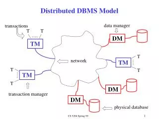
DISTRIBUTED DBMS ARCHITECTUREPEER-TO-PEER DISTRIBUTED SYSTEMS • The physical data organization on each machine may be different. • Local internal scheme (LIS) - is an individual internal schema definition at each site. • Global conceptual schema (GCS) - describes the enterprise view of the data. • Local conceptual schema (LCS) - describes the logical organization of data at each site. • External schemas (ESs) - support user applications and user access to the database.
DISTRIBUTED DBMS ARCHITECTUREPEER-TO-PEER DISTRIBUTED SYSTEMS
DISTRIBUTED DBMS ARCHITECTUREPEER-TO-PEER DISTRIBUTED SYSTEMS In these case, the ANSI/SPARC model is extended by the addition of global directory / dictionary (GD/D) to permits the required global mappings. The local mappings are still performed by local directory / dictionary(LD/D). The local database management components are integrated by means of global DBMS functions. Local conceptual schemas are mappings of global schema onto each site.
DISTRIBUTED DBMS ARCHITECTUREPEER-TO-PEER DISTRIBUTED SYSTEMS The detailed components of a distributed DBMS. Two major components: • user processor • data processor
DISTRIBUTED DBMS ARCHITECTUREPEER-TO-PEER DISTRIBUTED SYSTEMS User processor • user interface handler - is responsible for interpreting user commands as they come in, and formatting the result data as it is sent to the user, • semantic data controller- uses the integrity constraints and authorizations that are defined as part of the global conceptual schema to check if the user query can be processed, • global query optimizer and decomposer - determines an execution strategy to minimize a cost function, and translates the global queries in local ones using the global and local conceptual schemas as well as global directory, • distributed execution monitor - coordinates the distributed execution of the user request.
DISTRIBUTED DBMS ARCHITECTUREPEER-TO-PEER DISTRIBUTED SYSTEMS Data processor • local query optimizer - is responsible for choosing the best access path to access any data item, • local recovery manager - is responsible for making sure that the local database remains consistent even when failures occur, • run-time support processor - physically accesses the database according to the physical commands in the schedule generated by the query optimizer. This is the interface to the operating system and contains the database buffer (or cache) manager, which is responsible for maintaining the main memory buffers and managing the data accesses.
DISTRIBUTED DBMS ARCHITECTUREMDBS ARCHITECTURE Models using a Global Conceptual Schema (GCS) The GCS is defined by integrating either the external schemas of local autonomous databases or parts of their local conceptual schemas. If the heterogeneity exists in the system, then two implementation alternatives exists unilingual and multilingual. Models without a Global Conceptual Schema (GCS) The existence of a global conceptual schema in a multidatabase system is a controversial issue. There are researchers who even define a multidatabase management system as one that manages “several databases without the global schema”.
DISTRIBUTED DBMS ARCHITECTUREMDBS ARCHITECTURE - models using a GCS
DISTRIBUTED DBMS ARCHITECTUREMDBS ARCHITECTURE - models using a GCS • A unilingual multi-DBMS requires the users to utilize possibly different data models and languages when both a local database and the global database are accessed. • Any application that accesses data from multiple databases must do so by means of an external view that is defined on the global conceptual schema. • One application may have a local external schema (LES) defined on the local conceptual schema as well as a global external schema (GES) defined on the global conceptual schema.
DISTRIBUTED DBMS ARCHITECTUREMDBS ARCHITECTURE - models using a GCS • An alternative is multilingual architecture, where the basic philosophy is to permit each user to access the global database by means of an external schema, defined using the language of the user’s local DBMS. • The multilingual approach obviously makes querying the databases easier from the user’s perspective. However, it is more complicated because we must deal with translation of queries at run time.
DISTRIBUTED DBMS ARCHITECTUREMDBS ARCHITECTURE - models without a GCS
DISTRIBUTED DBMS ARCHITECTUREMDBS ARCHITECTURE - models without a GCS • The architecture identifies two layers: the local system layer and the multidatabase layer on top of it. • The local system layer consists of a number of DBMSs, which present to the multidatabase layer the part of their local database they are willing to share with users of the other databases. This shared data is presented either as the actual local conceptual schema or as a local external schema definition. • The multidatabase layer consist of a number of external views, which are constructed where each view may be defined on one local conceptual schema or on multiple conceptual schemas. Thus the responsibility of providing access to multiple databases is delegated to the mapping between the external schemas and the local conceptual schemas.
DISTRIBUTED DBMS ARCHITECTUREMDBS ARCHITECTURE - models without a GCS The MDBS provides a layer of software that runs on top of these individual DBMSs and provides users with the facilities of accessing various databases. Fig. represents a nondistributedmulti-DBMS. If the system is distributed, we would need to replicate the multidatabase layer to each site where there is a local DBMS that participates in the system.
DISTRIBUTED DBMS ARCHITECTUREGLOBAL DIRECTORY ISSUE • The global directory includes information about the location of the fragments as well as the makeup of the fragments. • The directory is itself a database that contains meta-data about the actual data stored in the database. • We have three dimensions: 1.type 2.location 3.replication
DISTRIBUTED DBMS ARCHITECTUREGLOBAL DIRECTORY ISSUE Type A directory maybe either global to the entire database or local to each site. In other words, there might be a single directory containing information about all the data in the database, or a number of directories, each containing the information stored at one site. Location The directory maybe maintained centrally at one site, or in a distributed fashion by distributing it over a number of sites. Replication There maybe a single copy of the directory or multiply copies.
DISTRIBUTED DBMS ARCHITECTUREGLOBAL DIRECTORY ISSUE These three dimensions are orthogonal to one another. The unrealistic combination have been designed by a question mark.
DISTRIBUTED DATABASE DESIGN The organization of distributed systems can be investigated along three orthogonal dimensions: 1. Level of sharing 2. Behavior of access patterns 3. Level of knowledge on access pattern behavior
DISTRIBUTED DATABASE DESIGN Level of sharing • no sharing - each application and its data execute at one site, • data sharing - all the programs are replicated at all the sites, but data files are not, • data plus program sharing - both data and programs may be shared. Behavior of access patterns • static - access patterns of user requests do not change over time, • dynamic - access patterns of user requests change over time. Level of knowledge on access pattern behavior • complete information - the access patterns can reasonably be predicted and do not deviate significantly from the predictions, • partial information - there are deviations from the predictions.
ALTERNATIVE DESIGN STRATEGIES Two major strategies that have been identified for designing distributed databases are: • the top-down approach • the bottom-up approach
ALTERNATIVE DESIGN STRATEGIESTOP-DOWN DESIGN PROCESS • view design -defining the interfaces for end users, • conceptual design - is the process by which the enterprise is examined to determine entity types and relationships among these entities. One can possibly divide this process into to related activity groups: • entity analysis - is concerned with determining the entities, their attributes, and the relationships among these entities, • functional analysis - is concerned with determining the fundamental functions with which the modeled enterprise is involved.
ALTERNATIVE DESIGN STRATEGIESTOP-DOWN DESIGN PROCESS • distributions design - design the local conceptual schemas by distributing the entities over the sites of the distributed system. The distribution design activity consists of two steps: • fragmentation • allocation • physical design - is the process, which maps the local conceptual schemas to the physical storage devices available at the corresponding sites, • observation and monitoring - the results is some form of feedback, which may result in backing up to one of the earlier steps in the design.
ALTERNATIVE DESIGN STRATEGIESBOTTOM-UPDESIGN PROCESS Top-down design is a suitable approach when a database system is being designed from scratch. If a number of databases already exist, and the design task involves integrating them into one database - the bottom-up approach is suitable for this type of environment. The starting point of bottom-up design is the individual local conceptual schemas. The process consists of integrating local schemas into the global conceptual schema.
DISTRIBUTION DESIGN ISSUESREASONS FOR FRAGMENTATION • The important issue is the appropriate unit of distribution. For a number of reasons it is only natural to consider subsets of relations as distribution units. • If the applications that have views defined on a given relation reside at different sites, two alternatives can be followed, with the entire relation being the unit of distribution. The relation is not replicated and is stored at only one site, or it is replicated at all or some of the sites where the applications reside. • The fragmentation of relations typically results in the parallel execution of a single query by dividing it into a set of subqueries that operate on fragments. Thus, fragmentation typically increases the level of concurrency and therefore the system throughput.
DISTRIBUTION DESIGN ISSUESREASONS FOR FRAGMENTATION • There are also the disadvantages of fragmentation: • if the application have conflicting requirements which prevent decomposition of the relation into mutually exclusive fragments, those applications whose views are defined on more than one fragment may suffer performance degradation, • the second problem is related to semantic data control, specifically to integrity checking.
DISTRIBUTION DESIGN ISSUESFRAGMENTATION ALTERNATIVES • The are clearly two alternatives: • horizontal fragmentation • vertical fragmentation • The fragmentation may, of course, be nested. If the nestings are of different types, one gets hybrid fragmentation.