Download
1 / 38
380 likes | 494 Vues
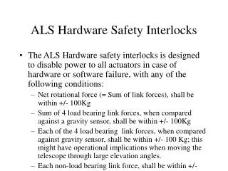
Machine Interlocks Systems Hardware readiness and plans State of the supervision. Bruno Puccio Pierre Dahlen Benjamin Todd Markus Zerlauth. Outline. Machine Interlocks = 5 systems managed by AB/CO Hardware readiness for: Powering Interlock System Warm magnet Interlock System

E N D
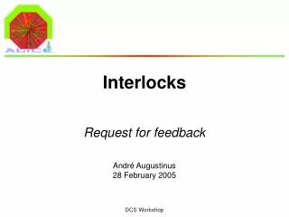
Machine Interlocks Systems Hardware readiness and plans State of the supervision Bruno Puccio Pierre Dahlen Benjamin Todd Markus Zerlauth
Outline • Machine Interlocks = 5 systems managed by AB/CO • Hardware readiness for: • Powering Interlock System • Warm magnet Interlock System • Fast Magnet Current change Monitor System • Safe Machine Parameters System • Beam Interlock System • Commissioning plans for IST of BIS • State of the supervision for the 5 systems • Summary
Machine Interlock Systems for Protecting Super ConductingMagnets and Normal Conducting Magnets for Protecting the Equipment for Beam Operation Beam Interlock System (VME based) Powering Interlock System (PLC based) + Safe Machine Parameters System (VME based) Warm magnet Interlock System (PLC based) Fast Magnet Current change Monitor (FMCM)
Common Approach BIS PIC Projects Design WIC SMP FMCM Fail Safe concept Reliability vs. Availability Redundancy Maintainability Critical functions in Hw Sw used only for Monitoring (in most cases) RS422
MI systems LHC Devices LHC Devices LHC Devices Movable Devices BCM Beam Loss Experimental Magnets Collimator Positions Environmental parameters BTV screens Mirrors Timing SMP Software Interlocks SEQ CCC Operator Buttons Experiments Transverse Feedback Beam Aperture Kickers Collimation System FBCM Lifetime BTV MKI Beam Dumping System Beam Interlock System Safe Beam Flag Injection BIS PIC essential + auxiliary circuits WIC FMCM BLM Access System Vacuum System RF System BPM in IR6 Timing System (Post Mortem) Monitors in arcs (several 1000) Monitors aperture limits (some 100) Magnets Power Converters Doors EIS Vacuum valves Access Safety Blocks RF Stoppers QPS (several 1000) Power Converters ~1500 AUG UPS Cryo OK Based on a R.Schmidt’s drawing Already commissioned during the HWC
Already deployed at CERN BIS already operational in SPS-LHC Transfer lines & CNGS (~ 90 User-Permits) and in SPS (~ 30 User-Permits) PIC operational WIC already operational in SPS-LHC Transfer lines & CNGS (~ 800 nc magnets) andin LEIR (~ 100 nc magnets) and already participating in HWC… FMCM already operational in both TL (14 monitors)
Powering Interlocks: PIC & WIC Beam Interlock System (VME based) Powering Interlock System (PLC based) + Safe Machine Parameters system (VME based) Warm magnet Interlock System (PLC based) Fast Magnet Current change Monitor (FMCM)
Powering Interlock Controllers: Readiness • 36 out of 36 Controllers are installed and ready to operate • Corresponding controls software is in place • As one of the key elements of the Powering part, the PIC system is regularly participating in the different phases of HWC Powering tests • Merit to our external collaborators • Warning: Support still needed if HWC beyond June 08 • 9PICs has been already commissioned within the sectors 7-8 and 4-5 • System ready for completing Powering tests… CIPA.L8 rack (front/rear views)
Warm magnet Interlock Controllers: Readiness • 8 out of 8 WICs installed and operational for HWC • Corresponding controls software is in place • 6 Controllers have been already commissioned • System ready for completing the Powering tests: • Point 2 planned for this week • Point 3 planned for week#13 • WIC in IP8 should be re-commissioned after MCBWH installation
Fast Magnet Current change Monitors Beam Interlock System (VME based) Powering Interlock System (PLC based) + Safe Machine Parameters system (VME based) Warm magnet Interlock System (PLC based) Fast Magnet Current change Monitor (FMCM)
FMCM: Overview Application • Protection against fast magnet current changes after powering failures • Hw based on DESY version. Main changes are: • Controls interface for supervision and PM readout • Connection with Beam Interlock System • TL/LHC mode selection • 12 monitors in the LHC: • D1 in IR1 and IR5 • Dump septa in IR6 • RD34, RQ4 & RQ5 in IR3, IR7, etc… • Monitoring via Serial link & VME Communication card (VIPC 626) Ethernet Technical Network VME crate Beam Interlock Controller VIPC626 CPU RS422 link FESA class + Existing driver for VIPC626 BIS
FMCM Readiness • 25 units out of 30 received from DESY and tested at CERN. ( 5 more to come) • Corresponding controls software is in place • System ready for installation (in March) • 17 units of the DESY version will also be purchased as backup solution for additional installations.
Safe Machine Parameters project Previously named Safe LHC Parameters (SLP) Beam Interlock System (VME based) Powering Interlock System (PLC based) + Safe Machine Parameters system (VME based) Warm magnet Interlock System (PLC based) Fast Magnet Current change Monitor (FMCM)
Safe MachineParameters: quick overview Clients Safe Machine Parameters Controller LHC Timing Generator Data sources • For the LHC: Data sources Data sources • Interfaces with: • - Kicker system (BETS) • Slow BCT • Fast BCT • Sequencer • MCS • The LHC Parameters are: • Beam Energy • Safe_Beam_Flags (Beam-1, Beam-2) • Beam_Presence_Flag • Stable_Beam_Flag • Movable_Device_Allowed_in_Flag • Clients: • - BLM • Injection Kickers • Experiments • BIS Basic layout Timing Network • For the SPS: • Interfaces with: • - Kicker system (BETS) • BCT • The SPS Parameters are: • Safe_Beam_Flag • Probe_Beam_Flag • LHC_Beam_Flag • CNGS_Beam_Flag • Clients: • - Extraction-BIS • SPS-BIS • Generation of critical parameters + Distribution over the Timing network
Safe Machine Parameters system:Readiness • Two SMP variants: one for LHC and one for SPS • In both cases, a single controller (VME crate with several dedicated boards)is needed • Project done in collaboration with CO-HT section • Prototype version available: • BIS Concepts re-used (Simple, Safe, Fail-Safe concept, Safety part separated from Monitoring part,…) • First version will ready for SPS start-up • LHC variant will be ready in June 08 • Preliminary version foreseen on week#15 for the distribution of Energy value prototype system running in the LAB • Final version in 2009: • No difference on Client side. Effort put on Monitoring & on Safety: • including redundant sources for E and for I • including redundant process • including cross-check of Timing distribution
Beam Interlock System Beam Interlock System (VME based) Powering Interlock System (PLC based) + Safe Machine Parameters system (VME based) Warm magnet Interlock System (PLC based) Fast Magnet Current change Monitor (FMCM)
BIS Architecture: quick overview CIBU BIC CCR Designed to be: - Simple (Green/Red nothing else) - Safe, Fast, Available, - “Fail safe state” implementation - “Easy to monitor” OR
BIS: Readiness • 17 out 17 BICs for LHC ring BIS are installed • 2 Controllers for Injection BIS as well • 90% CIBU already installed (waiting for access for the remainder) • 95% cables tested (waiting for access for the remainder) • IST is pending => F.O. not yet installed • TS/EL working on it with the highest priority…
Outline • Machine Interlocks = 5 systems managed by AB/CO • Hardware readiness for: • Powering Interlock System • Warm magnet Interlock System • Fast Magnet Current change Monitor System • Safe Machine Parameters System • Beam Interlock System • Commissioning plans for the BIS • State of the supervision for the 5 systems • Summary
BIS Commissioning Phases BIS installation and commissioning: a 3 phase programme • Complete the IST of the BIS by April • generally speaking: independent of the HWC. • Perform the Commissioning of the BIS in parallel with the HWC. • As BICs are installed on each side of an IP => done for each of the 8 points. • Test each link in involving the different USER SYSTEMS • Perform a final test with all players (includes LBDS, Beam Sequencer and Timing) Participation in Dry runs: • Installed 2 more BICs in Pt 6 for LBDS dry-runs in parallel with BIS commissioning. • Goal: permit BIS commissioning + also test interfaces with Kickers, SEQ & Timing.
Dry-runs in // with BIS commissioning SEQ LHC Timing Gen. LHC Timing Network “Dump Beam-2” Event “Dump Beam-1” Event Tests of Programmed Beam Dump provoked by the SEQ via Timing System LBDS-1 User Systems Beam_1 User Permits_1 BEAM_PERMIT_1 LHC-BIS Beam-1 User Permits_(1+2) User Systems Both-Beams LHC-BIS Beam-2 User Permits_2 User Systems Beam_2 LBDS-2 BEAM_PERMIT_2 Unlink BIS1 / BIS2 Sequencer loads Timing table containing “Dump Beam-1” event (or “Dump Beam-2” )
LHC systems connected to the BIS CIBU CIBU CIBU CIBU CIBU CIBU CIBU CIBU CIBU CIBU CIBU CIBU CIBU CIBU LHC Devices LHC Devices LHC Devices Movable Devices BCM Beam Loss Experimental Magnets Collimator Positions Environmental parameters BTV screens Mirrors Timing SMP Software Interlocks SEQ CCC Operator Buttons Experiments Transverse Feedback Beam Aperture Kickers Collimation System FBCM Lifetime BTV MKI 2 2 42 4 2 2 2 9 2 2 15 2 Beam Dumping System Beam Interlock System Safe Beam Flag 12 32 8 4 32 2 16 1 Injection BIS PIC essential + auxiliary circuits WIC FMCM BLM Access System Vacuum System RF System BPM in IR6 Timing System (Post Mortem) Monitors in arcs (several 1000) Monitors aperture limits (some 100) Magnets Power Converters Doors EIS Vacuum valves Access Safety Blocks RF Stoppers QPS (several 1000) Power Converters ~1500 AUG UPS Cryo OK Number of User_Permit links
BIS Connections: the Layout User System’s location: id. BIC location ~55% in US/UX ~12% ( in UJ & RR ) ~22% ( surface ) ~11% SR 2 SR 5 SR 6 SR 4 SR 1 SX 4 SR 8 USC55 UA47 SR 3 SR 7 UJ56 UA43 SR3 UA47 UA43 UA83 CCR UA27 USC55 US152 UA63 UA67 TZ76 UA23 UA87 US151 UJ56 UA63 UX25 US85 US65 UX45 UX85 UJ33 UA67 UJ33 RR77 RR13 RR17 RR57 RR73 RR53 SR7 UA27 TZ76 CCR UA23 UA83 UA87 US15 US15 UJ76 UJ14 UJ16 BIC location
IST of the Beam Interlock System CIBU Individual System Test 2 redundant F.O. links previous/next BICs Status at the end of IST: • 17 ring BICs are installed and all connected together (2 INJ BICs as well) • All CIBUs installed and corresponding links tested. •Verification that installed Hw can be monitored and logged via the Supervision. •Fiber patches are close to the final configuration (LBDS still not included). •Propagation delays are known. All steps stored in MTF
Phase 2 It is asked to change the User_Permit_A & User_Permit_B separately Details given in the Procedure document : https://edms.cern.ch/file/889281/1/MPS-BIS-Commissioning_v1.pdf User Permit_A 2 redundant F.O. links CIBU OR previous/next BICs User Permit_B Beam Info II User Systems included in the Commissioning See also Alick’s talk (“Machine Interlocks” in Session 2)
LBDS link checks at the end of Phase 2 LBDS Beam-1 trigger LBDS Beam-2 trigger III Beam Interlock System Commissioning Note: Functionality and Interfaces previously tested during LBDS Dry-runs
Different steps described in MTF MTF Structure for MPS being defined Test version exists Will soon move to production environment MTF structure based on procedures in EDMS Courtesy of A.MACPHERSON
BIS Commissioning Schedule • Time allocation for phase 2: • Allocate 8 periods of ~5 days (or twice 2,5 days) during the HWC. • These slots will be either just before or just after sector powering tests • Sequence not important: Priority to Pts 8, 7 and 6 in case of Sector test fallback • Proposal still in discussion with the planning team • Expect these slots to be in May/June (It depends on HWC progress). • Time allocation for phase 3: • Need a dedicated week during the cold-checkout period • See Jan Uythoven’s talk (“Machine Protection” in Session 4)
Outline • Machine Interlocks = 5 systems managed by AB/CO • Hardware readiness for: • Powering Interlock System • Warm magnet Interlock System • Fast Magnet Current change Monitor System • Safe Machine Parameters System • Beam Interlock System • Commissioning plans for IST of BIS • State of the supervision for the 5 systems • Summary
MI Systems = Vertical slices in Control system Through MI systems, AB-CO has the function of an equipment group we should be the first to use CO standard tools AB-OP Application tier MW PVSS Middle-tier AB-CO FESA CO-services BIC or SMP or FMCM PIC or WIC Front-End tier AB-EQ Integration done in collaboration with CO-FE, CO-DM, CO-AP and CO-IS Courtesy of H.Schmickler
PIC Supervision: operational in CCC Courtesy of Frederic Bernard (AB/CO/IS)
WIC Supervision: operational in CCC Courtesy of Frederic Bernard (AB/CO/IS)
FMCM Supervision: available in CCC Courtesy of Nicolas Hoibian (AB/CO/AP)
SMP Supervision • So far, there is no SMP Supervision • Basic version will be available in June 08 • Final version for 2009
BIS Supervision: operational in CCC Example with SPS-BIS: Inputs Safe Beam Flag status Output Inputs 1 to 7 are unmaskable History Buffer screen Inputs 8 to 14 are maskable Extraction Permit screen Mask status
BIS Supervision: LHC specifics ongoing Courtesy of A.MACPHERSON Internal Post Operation Check (IPOC) of the BIS not yet available => Expected in the near future
Wrapping up • MI Systems = Technical solutions well established and tested • PIC & WIC : ready for completing the Powering tests • FMCM: ready for commissioning • SMP: First version ready for beam operation • Final version (Hw + Application) in 2009 • BIS will be ready for Beam Operations • Hw in place. IST temporarily stopped. • Controls Sw in place. Need effort on IPOC. • Faced to a Challenging Commissioning • Profit for past experience in TL & in SPS • Fruitful collaboration with OP & MPSC Working Group