Optimizing Internal Multiple Attenuation Techniques in Seismic Data Processing
520 likes | 544 Vues
An in-depth review of practical approximations and challenges in Internal Multiple Attenuation methods for seismic data processing. The discussion covers various techniques, including Inverse Scattering, Wavelet and Subtraction issues, Transmission effects, and more. While the methods are effective, there is room for improvement.

Optimizing Internal Multiple Attenuation Techniques in Seismic Data Processing
E N D
Presentation Transcript
MOSRP Multiple Attenuation Review Ken Matson, BP EPTG, Houston Nov, 2003
Outline • 2D Free-Surface Demultiple (SRME) approximations in practice: what can go wrong? • Internal multiple attenuation • Inverse Scattering • How and why does it work • Wavelet and subtraction issues as compared with SRME • Effect of transmission on amplitudes • Delphi Internal Demultiple • Layer and interface methods • How and why do they work? • Relationship to Inverse Scattering method
Some practical approximations made in 2D SRME application • 3D Earth (assumes 2D earth shot in dip direction) • 3D acquisition geometry (e.g.,feather, multi-cable shooting) • Single term prediction followed by minimum energy adaptive subtraction (e.g., potential damage to primaries, less effective in shallow water). • Minimum energy wavelet estimation (e.g.,corrupted by 3D effects above) • Missing near (and far) offsets and inadequate methods to estimate them • Aliasing • Missing shots (coarse shot interval or gaps in shooting) • Obliquity factor missing • Ghosts not removed • Source and receiver depths not corrected • Air-water interface not a perfect free-surface (sea state?) • Source and receiver arrays not corrected for • 3D -> 2D amplitudes not properly corrected for • Direct wave not removed (e.g., water too shallow to mute) • …
Despite these approximations, the method still works very well … Input Output But there is room for improvement …
Some practical approximations made in 2D SRME application • 3D Earth (assumes 2D earth shot in dip direction) • 3D acquisition geometry (e.g.,feather, multi-cable shooting) • Single term prediction followed by minimum energy adaptive subtraction (e.g., potential damage to primaries, less effective in shallow water). • Minimum energy wavelet estimation (e.g.,corrupted by 3D effects above) • Missing near (and far) offsets and inadequate methods to estimate them • Aliasing • Missing shots (coarse shot interval or gaps in shooting) • Obliquity factor missing • Ghosts not removed • Source and receiver depths not corrected • Air-water interface not a perfect free-surface (sea state?) • Source and receiver arrays not corrected for • 3D -> 2D amplitudes not properly corrected for • Direct wave not removed (e.g., water too shallow to mute) • …
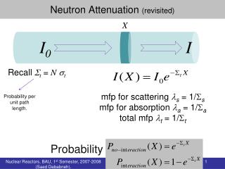
Free-surface multiple Internal multiple Internal Multiple Attenuation All downward reflections below the air-water interface One or more reflections from the air-water interface
Free-surface multiple prediction (SRME) Multiples are predicted by the time convolution of subevents Sub-event 1 Sub-event 2 a b c
Inverse Scattering Internal Demultiple • Requires no subsurface information • Predicts the arrival time of all internal multiples exactly • Predicts the amplitudes of internal multiples approximately • (Much) more computationally demanding than free-surface multiple attenuation
b1(t2) b1(w)b1(-w)b1(w) b1(t1) b1(t3) Inverse Scattering Internal demultiple:1D version For all interfaces:
SE1(w)SE2(-w)SE3(w) Inverse Scattering Internal demultiple:1D version • For a selected 3 subevents that satisfy the lower-higher-lower criteria: Sub-event 2 a b c d Sub-event 1 Sub-event 3
SE1(w)SE2(-w)SE3(w) Inverse Scattering Internal demultiple:1D version • After the convolution and crosscorrelation of these subevents, this gives: a d Prediction of internal multiple with exact kinematics
Inverse Scattering Internal demultiple:1D version • How accurate is the amplitude prediction? Actual multiple amplitude= (1-r1) *r2 *(-r1) *r3 *(1+r1) transmission effects r1 r2 r3
Inverse Scattering Internal demultiple:1D version • Subevent amplitudes Sub-event 2 r1 a b c d Sub-event 1 (1-r1) *r2 *(1+r1) Sub-event 3 (1-r1) *r3 *(1+r1) r1 r2 r3
Inverse Scattering Internal demultiple:1D version • Actual multiple amplitude: = (1-r1) *r2 *(-r1) *r3 *(1+r1) • Predicted multiple amplitude: = -1*(1-r1) *(1-r1) *r2 *(-r1) *r3 *(1+r1)* (1+r1) Excess transmission due to these paths: Fortunately, (1-r12) is small, so the error is small
Inverse Scattering Internal demultiple • The algorithm computes this operation for all possible combinations of three subevents in the data that satisfy the lower-higher-lower criteria, thereby predicting all the possible multiples in the data (including converted waves) • 2D (and 3D) version contains a more complicated operation across the spatial coordinates, but in pseudo-depth (travel time), it works the same as the 1D code. • Will not predict internal multiples that are sub-wavelet length in scale. Prediction requires events that are resolvable.
Wavelet issues with internal multiple attenuation • Method assumes that the free-surface multiples have already been removed. It has the same data pre-requisites as the free-surface procedure, so the post SRME data should be well suited to internal demultiple • BUT, using the standard SRME flow of estimating the wavelet post-multiple prediction is much more dangerous for internal multiples because minimum energy can easily be violated for internal multiples, even for large data windows. A safer approach is to use the SRME wavelet estimate and remove this wavelet prior to internal multiple prediction.
Wavelet issues with internal multiple attenuation Data flow: • Free-surface multiple removal (wavelet estimated) • Deconvolve SRME output data with estimated wavelet • Predict internal multiples (single order prediction) • (Mild) adaptive subtraction. • Minimum energy criteria for multiple removal is less valid for internal multiples as compared to free-surface case; therefore, the subtraction has to be carefully constrained. • Even with the source wavelet deconvolved, there is often a residual effective wavelet (finite bandwidth and limited ability of decon to flatten spectrum)
Wavelet issues with internal multiple attenuation • Unlike the free-surface case, the effective wavelet on the internal multiple prediction has the same phase as the input data; the amplitude spectra of this wavelet differs by the autocorrelation of the source wavelet. • Why? • Consider input data with wavelet a = a(w) b1(w) • Internal multiple prediction computed using particular subevents a(w) SE1(w)a (-w)SE2(-w) a(w)SE3(w) =a(w) a(-w)a(w) [SE1(w)SE2(-w) SE3(w)] = a(w)A(w) [SE1(w)SE2(-w) SE3(w)] Zero phase (autocorrelation of wavelet)
1.6 Seconds 4.6 Mississippi Canyon Original stack Stack after free-surface demultiple Water bottom Top salt Base salt Free- surface multiples
1.6 0 ms Seconds 400 4.6 Mississippi Canyon Stack after free-surface demultiple & source wavelet deconvolution Average estimated source wavelet Water bottom Top salt Base salt
1.6 Seconds 4.0 Mississippi Canyon 1-D post-stack internal multiple estimate Stack of 2-D pre-stack internal multiple estimate Stack of input data Water bottom Top salt Base salt
1.7 Seconds 3.4 Mississippi Canyon Input Predicted multiples Output Input Predicted multiples Output Water bottom Top salt Base salt Internal multiples Common Offset Panel (1450 ft) Common Offset Panel (2350 ft)
Mississippi Canyon Water Bottom Top Salt Base Salt Internal multiple Water Bottom Top Salt Top Salt Base Salt
Southern Gas Basin Post-stack 1-D internal multiple estimate Stack after Tau-p decon & Radon Primary Primary Primary Internal Multiple Seismic data come from a non-exclusive survey owned by Geco-Prakla. Permission to use this data is gratefully acknowledged.
Southern Gas Basin Primary Primary Primary Internal Multiple
Southern Gas Basin Stack after Tau-p decon & Radon 1-D post-stack internal multiple prediction After internal multiple adaptive subtraction Internal multiples Seismic data come from a non-exclusive survey owned by Geco-Prakla. Permission to use this data is gratefully acknowledged.
Southern Gas Basin Data after WEMS, Tau-p decon & Radon 2-D pre-stack internal multiple prediction Data after adaptive subtraction Common offset gathers (1000 ft) Seismic data come from a non-exclusive survey owned by Geco-Prakla. Permission to use this data is gratefully acknowledged.
Offset Southern Gas Basin Raw shot gather after NMO After internal multiple subtraction Predicted 2-D internal multiple After Tau-P decon, WEMS, Radon Seismic data come from a non-exclusive survey owned by Geco-Prakla. Permission to use this data is gratefully acknowledged.
Offset Southern Gas Basin After Tau-P decon, WEMS, Radon Raw shot gather after NMO After internal multiple subtraction Predicted 2-D internal multiple Seismic data come from a non-exclusive survey owned by Geco-Prakla. Permission to use this data is gratefully acknowledged.
Southern Gas Basin AVO ‘A’ Section Before internal multiple attenuation After internal multiple attenuation Seismic data come from a non-exclusive survey owned by Geco-Prakla. Permission to use this data is gratefully acknowledged.
Southern Gas Basin AVO ‘B’ Section Before internal multiple attenuation After internal multiple attenuation Seismic data come from a non-exclusive survey owned by Geco-Prakla. Permission to use this data is gratefully acknowledged.
Inverse-scattering internal multiple attenuation conclusions • Effectively attenuates internal multiples on synthetic and field data • Subsurface independent; applicable to data with simple or complex geology (no a-priori information required) • Requires accurate source wavelet removal • Highlights need for improved subtraction processes
Delphi Internal Demultiple Methods • Interface Based • Layer Based • Relation to Inverse Scattering Method
Delphi Interface Method a b c d Sub-event 2 Sub-event 1 Internal multiple generating interface
Delphi Interface Method Downward continue these paths to the interface where the internal multiple is generated a b c d Sub-event 2 Sub-event 1
Delphi Interface Method Now convolve these two subevents as in SRME to obtain a kinematic prediction of the internal multiple. a d SE1(w)SE2(w) Sub-event 2 Sub-event 1 In principle, the interface reflectivity must be provided.
Delphi Interface Method • Essentially the free-surface multiple prediction concept applied to a subsurface reflector • Requires: • Proper downward continuation to the interface of interest. Needs explicit velocity model or CFP operators (model dependent). • Source wavelet • Effective wavelet on the prediction has the same amplitude and phase error as the SRME prediction. Estimating this wavelet by matching the prediction to the multiples in the input data is much more hazardous than in the free-surface case. Probably better to remove the source wavelet prior to multiple prediction (as in the Inverse Scattering flow) • Estimate of interface reflectivity • Often this unknown is bundled into an adaptive subtraction. Similar to the source wavelet estimation, this has to be done very conservatively to preserve primaries.
Delphi Layer Method Downward continue these paths to a point below the interface where the internal multiple is generated Sub-event 2 a b c d Sub-event 1 Sub-event 3 Internal multiple generating interface Target depth (time) for downward continuation
Delphi Layer Method Downward continue these paths to a point below the interface where the internal multiple is generated Sub-event 2’ a b c d Sub-event 1’ Sub-event 3’ Internal multiple generating interface Target depth (time) for downward continuation
Delphi Layer Method • To predict the internal multiple, perform the operation SE’1(w)SE’2(w) SE’3(w) a d Sub-event 2’ Sub-event 1’ Sub-event 3’ Internal multiple generating interface Target depth (time) for downward continuation
Delphi Layer Method • Giving the prediction of the internal multiple: a d
Delphi Layer Method • How does this work? • Apply downward continuation operator to subevents: T = time to target depth Sub-event 2’= exp(iwT) SE2 (w)exp(iwT) Sub-event 3’= exp(iwT) SE3(w) Sub-event 1’= SE1(w) exp(iwT)
Delphi Layer Method Apply the operation to obtain: SE’1(w)SE’2(-w) SE’3(w) SE1(w) exp(iwT) exp(-iwT) SE2(-w) exp(-iwT) exp(iwT) SE3 (w) = SE1(w) SE2(-w) SE3 (w) • The downward continuation operators cancel, and you obtain the proper prediction • Why do the downward continuation at all? Delphi claims that the event separation (muting) is best done in the downward continued domain. • The subevents carry the amplitude information similar to the Inverse Scattering Method
Delphi Layer Method • This works for a single interface as shown, how does the method work for a series of reflectors, i.e., a layer? Multiple Prediction Interface 1 A B1* C Interface 2 A B2* C A B3* C Interface 3
Delphi Layer Method • Sum these: Multiple Prediction Interfaces 1,2 and 3 A (B1 + B2 + B3) * C and by extension A (BN) * C where BN represents the series of reflectors above the target separation depth. This approach predicts all internal multiples that contain a downward reflection above the target depth and upward reflections below the target depth.
Delphi Layer Method • This approach is efficient and effective but does not predict multiples that look like: To predict these events, you would have to iteratively define a separation time that separates the top reflector from the rest of the reflectors, predict the internal multiples, remove this top reflector, and then continue doing this for all the reflectors from the top down. This would then emulate the Inverse Scattering algorithm which does all this automatically without all the user interaction.
Delphi Layer Method First Second Third
Delphi Layer Method • Efficient way to predict a selected subset of multiples. • Requires: • Downward continuation to an interface that separates the upward from downward reflectors. CFP operators used, does not need to be accurate (in that way, it is subsurface independence). • Source wavelet • Has the same characteristics as the Inverse Scattering Method as far as the wavelet is concerned. • Adaptive subtraction • Must be careful, as subtraction can easily damage primaries. • May have advantage in terms of correcting for the depth dependent transmission effects by stepwise generating different predictions for different depths.
Internal Multiple Attenuation Comparison • Delphi method(s) are well suited when you have small number of strong internal multiple generators that are easily separable. These methods will efficiently and effectively predict the most important internal multiples in this situation. • The Inverse Scattering Method is useful when you have a large number of internal multiple generators that are not easily separable. This method will predict everything at once without user interaction, but at increased computation time/cost. • In this way, the two types of methods are complementary and both should be included in your processing toolbox.
Conclusions • There are plenty of approximations made in applying 2D SRME in practice. Improving the most egregious of these will further improve our ability to remove multiples in complex situations. • Inverse Scattering and Delphi layer based method are different but complementary methods that are useful for different situations • Both are subsurface independent • Both suffer from lack of accurate wavelet information • Both require a more fit for purpose set of subtraction tools • Both require adequate removal of free-surface multiples to reach their full potential (or very deep water).