Anatomy of an Aircraft
Anatomy of an Aircraft. A look at the parts and components which make up an aircraft And what they do. Aircraft come in many different sizes and configurations, depending on what they are used for. A beginner's guide to the various sections of aircraft.

Anatomy of an Aircraft
E N D
Presentation Transcript
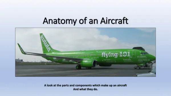
Anatomy of an Aircraft A look at the parts and components which make up an aircraft And what they do.
Aircraft come in many different sizes and configurations, depending on what they are used for
A beginner's guide to the various sections of aircraft. • We take a basic look at what makes up an aircraft, the names and functions of the major parts or elements. • Body, or Fuselage as it is known. • Wings. • Tail • Engines • Landing gear (or wheels) In the following pages we will deal in a little more detail.
Fuselage Aircraft fuselage (or body)
Fuselage information: The fuselage comprises of the following compartments: The Flight deck in the front where the pilots are located. Passenger compartments (Including passenger doors, emergency exits, Galleys and toilets) Cargo/baggage compartments, located below the passenger compartments In some aircraft extra fuel tanks are also located below the passenger floor. Passenger doors Emergency exits Cargo doors
Wings The wings provide lift for the aircraft allowing it to fly. The wings are fitted with control surfaces which assist in increasing the wing are for more lift, turning the aircraft, slowing it down for landing. See following slide for more information. Engine fuel tanks are also fitted in the wings.
A Closer look at the wing! Components of the wing: Leading edge flaps (marked 1) – used to increase the wing area and provide more lift during take off and landing. Spoilers, (Marked “2”)or speed brakes, these are extended to help slow the aircraft down when coming in to land. They are also used in flight to assist ailerons to turn aircraft. Ailerons. This aircraft has 2 sets of ailerons, marked “3” Trailing edge flaps: (Marked 4) also used to increase wing area to provide more lift for take off. For landing, they also serve to slow the aircraft down and decrease lift. 1 2 4 3
A wing “in action” on landing (Boeing 737) Spoilers/speed brakes extended Flaps fully extended
Engines 4 piston engines, propeller engines for old DC4 Skymaster Three jet engines for MD-11 aircraft Two jet engines for A320 aircraft Most modern commercial airliners use Turbofan Jet engines, or Turbo prop jet engines. Older aircraft were fitted with piston engines, driving propellers
Engine notes: • When working near running engines, ensure that you keep a safe distance from both the front and rear of the engines. • In the case of propeller engines, stay clear of propellers, a number of people have been killed by rotating propellers! • With Jet engines, stay clear of both the front and rear of the engines, safe areas are usually marked for the front of the engine, people have been sucked into engines and killed. The rear of the engine is also dangerous, the exhaust gases are very hot and the thrust from the exhaust can easily blow a person, or even vehicles away. Refer also to lesson on “Safety around aircraft” course for more details.
Engine notes continued: To give an example of the danger areas we show below the info on the A380 aircraft with engines at idle power. Picture 1 shows exhaust gas temperatures and picture 2 shows “danger areas” around aircraft and engines. Pictures courtesy Airbus A380 Airport and Maintenance Planning manual
Empennage (Also known as Tail plane) Vertical Stabilizer Horizontal Stabilizer
Notes on Vertical and horizontal stabilizers • The vertical stabilizer is fitted with a control called the rudder which assists the aircraft to turn in flight. It also stops “yawing” of the aircraft in flight (stops aircraft from swinging from side to side) • The horizontal stabilizer is also fitted with control surfaces known as elevators which when moved, allow the aircraft to climb or descend during flight. On many large aircraft, the entire horizontal stabilizer and be adjusted up or down to enable straight and level flight.
Landing gear The aircraft landing gear is required to allow the aircraft to move safely on the ground and naturally for steering the aircraft on the ground and for take off and landings. During flight the landing gear is retracted to reduce drag Boeing 747 Airbus A320 Antonov 124 nose gear Boeing 777 Airbus A340-600 Antonov 124 Main gear
Landing gear continued…. • Some information on landing gear – “How many wheels?” On the previous slide, we showed a few photos of landing gear. To give a better idea, here are a few examples of aircraft and how many wheels are fitted: • Boeing 737 – 4 on main landing gear and 2 nose wheels. Total 6 wheels • Boeing 747 – 16 main gear wheels and 2 nose wheels. Total 18 wheels. • Boeing 777 – 12 main gear wheels and 2 nose wheels. Total 14 wheels • Antonov 124 – (large Cargo aircraft) 20 main gear wheels and 4 nose wheels! Total 24 wheels! • Airbus A340-600 – 12 main gear wheels and 2 nose wheels. Total 14 wheels. • Airbus A320 – 4 main gear wheels and 2 nose wheels. Total 6 wheels. The number and size of wheels depends on the size and weight of the aircraft.
Other “Q & A’s” from observations We have been asked on occasions where people have noticed “Objects” on aircraft and wondered what they were and what purpose they served. In this presentation we will show some of the items we have been asked about and provide a basic description of the items. No “in depth” discussions or explanations at this stage, just the basics.
A question which has been asked often is “What are the red flags/ribbons/covers that one sees on the aircraft on the apron or in hangars?” Example of steering lockout pin These items, usually red or orange are all safety related items, which are fitted to aircraft on the ground. As the markings show, these must be removed before flight. It will be seen that the items are Engine intake covers, Pitot head covers, static port covers Landing gear lock pins, steering lock out pins, to name a few. ) The covers are fitted to prevent and “FOD” (Foreign object debris dirt) from entering into the items mentioned, Landing gear lock pins prevent the landing gear from being retracted with the aircraft on the ground and the steering lock out pins disable hydraulic steering on nose gear when towing or pushing aircraft on the ground
Other probes and sensors As with road vehicles, aircraft are also fitted with instruments (A whole lot more than for road vehicles!) to keep Pilots informed as to the aircraft’s performance at all times. We will not go into all of these here, but just touch on a few critical items required for safe flight. Some of the probes and sensors shown earlier – (Red flags ribbons etc.) It will be seen on aircraft, that there are always more than one of each type of probe/sensor for safety/back-ups, in case of sensor failures. Angle of attack sensor – Angle of attack sensor indicates the angle at which the aircraft is either climbing or descending. Very important instrument to assist pilot especially during landing and landing. Static ports – These ports measure the ambient air pressure of an aircraft in flight Pitot heads – Pitot heads are used to determine an aircraft’s speed in fight
Static Discharge Wicks Static Discharge Wicks are fitted to the trailing edges of the wing and tail planes of modern aircraft, as pointed out here by Tom Considine. The friction caused by the aircraft flying through the air causes a buildup of static electricity which could result in sparks being generated, which could be dangerous. (Similar to when a person rubs/strokes a cat). These discharge wicks discharge the static electricity into the air safely and with no sparking.
Vortex Generators Vortex generators look like tiny wings fitted in upright position on wings and in come cases on aircraft vertical stabilizers. During high speed flight, the airflow over the wings and rudder, tends to “lift” causing the control surfaces (Ailerons and rudder) to “work in a vacuum” and become ineffective. The vortex generators create turbulence in the airflow, keeping the airflow over the wing from “Lifting” off and the control surfaces remain effective. Vortex generators on B737 wing Low speed flight High speed flight (Airflow shown in red)
Lights Another question sometimes asked is “What lights do aircraft have”? The following pages will show and explain generally what lights are fitted, where they are fitted and their purpose. Numbering of A380 engines #1 #2 #4 #3 #1 eng #2 eng Before we get there, a reminder of how the Engines, Landing gear etc. are identified. Simple, when standing behind the aircraft, facing the front of the aircraft, items are numbered from left to right as shown above. Remember too – Port is left side - Red and starboard is right side - Green
Lights Aircraft are fitted with a number of lights, (mostly very bright!) These all serve a very important purpose as will be explained. Examples of these will be shown over the next TwoPages. The first lights we will look at, are “anti collision lights”: These are red lights (Flashing or strobe lights) and are mounted on the roof of the aircraft and belly. They are switched on just engine start up and are only switched off after the aircraft has landed, parked and engines are shut down. These lights basically serve Two purposes – 1. to warn personnel on the ground that the aircraft engines are running and personnel need to be clear of the aircraft. 2. In flight, especially at night, the lights will be visible to other aircraft warning them of the presence of another aircraft in the area. Upper light Lower Light
Lights - 2 Navigation lights: two navigation lights are fitted to aircraft (in the case of commercial aircraft) – one on each wing tip. The left hand wingtip (Port wing) is red and the right hand wingtip (Starboard wing) is green. These lights indicate the direction that the aircraft is moving especially at night. Again, at night, other aircraft will immediately see whether other aircraft are approaching them, or if they are flying in the same direction. Port “Nav” light -Red Starboard “Nav” light - Green
Lights - 3 Landing and Taxi lights: Landing lights (extremely powerful) are fitted to the nose landing gear, as well as the wings (Usually near wing roots). The number and position of landing lights fitted varies per aircraft size. At night they are switched on when aircraft is lined up on runway, ready for take off. These lights illuminate the area in front off the aircraft, assisting the pilot during take off safely, The lights are switched off when the aircraft reaches an altitude of 10 000ft (again, serving to alert any other air traffic as to its presence). During the landing phase, these lights are switched on at 10 000ft, also to alert other traffic to its presence. The lights are switched off when the aircraft turn off the runway onto the taxiway. Taxi lights are used at night to illuminate the area in front of the aircraft while taxiing to the runway. These lights would usually be switched off after take off. On landing, they would usually be switched on with the landing lights. They are left on, usually until the aircraft turns into the parking bay. (so as not to “blind” ground staff!) Taxi lights Landing lights
In Conclusion • This short presentation covers the very basics of what makes up aircraft. • Obviously, there is a great deal more involved in the manufacture of aircraft , including extensive use of Computer technology, sophisticated technical aspects, and safety aspects and aids to the flight deck crew to ensure safe and efficient flight. • For more comprehensive and information interesting courses, links to other aviation related websites, studies and other comprehensive documentation on various aspects of aviation, we strongly recommend that you visit The Air Transport Research Institute (ATRI) website https://atrisa.wordpress.com It is well worth the time! • We trust that you have enjoyed this introduction to aircraft. Thank you for your time!