
Training Course Channel Estimation
E N D
Presentation Transcript
Training CourseChannel Estimation 2011/08/08 蒲俊瑋
Outline • Introduction • Channel Estimation Techniques in OFDM Systems • LS Channel Estimation • Linear Interpolation Channel Estimation • MMSE Channel Estimation • MLS Channel Estimation • Channel Estimation Techniques Based on Pilot Arrangement in OFDM Systems • Channel Equalization in Timing Varying Channel
Small Scale Fading • Multi-path channel
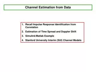
Channel Impulse Response • A mobile radio channel may be modeled as a linear filter with a time varying impulse response, where the time variation is due to receiver motion in space. • The filtering nature of the channel is caused by the summation of amplitudes and delays of the multiple arriving waves at any instant of time.
Channel Impulse Response EX: Data = [1 2 3 4] Channel = [1 1] y = 1 2 3 4 1 2 3 4 = 1 3 5 7 4 path1 path2
The Matrix Form of Channel • The wireless stationary channel impulse response is given by , where L is the total number of resolvable paths. • We assume that each tap of the channel impulse responses , , are independently distributed complex Gaussian random variables with zero-mean and variance .
The Multi-Path Channel Effect • The multi-path channel effect • 2 3 4 • 1 2 3 4
The Matrix Form of Channel • The matrix G is constructed as follows: EX: Data = [1 2 3 4] Channel = [1 1]
The Matrix Form of Channel • The matrix is constructed as follows: CP
The Matrix Form of Channel • Furthermore, a circular convolution matrix can be obtained:
The Transmitted OFDM Signal • After the inverse discrete Fourier transform (IDFT) operation, the ith transmitted OFDM symbol in time domain can be expressed by: where and are an vector and an matrix standing for modulated symbols and an IDFT matrix.
The Received CP-OFDM Symbol • Assuming the synchronization is perfect and CP is adopted, the received ith OFDM symbol can be expressed as: where denotes the circular convolution and denotes the additive white Gaussian noise (AWGN) vector in the time domain with zero mean and variance . We note that there is no ICI and ISI in each OFDM symbol.
The Received CP-OFDM Symbol • After DFT operation, the ith received OFDM symbol in the frequency domain can be expressed as: where is the AWGN in the frequency domain and H is a diagonal matrix denoting the channel response in frequency domain.
The Received CP-OFDM Symbol • Any circular matrix can be diagonalized by DFT matrix: • The received signal can be expressed as:
The Received OFDM Signal • Assuming the synchronization is perfect and CP is not adopted, the ith received OFDM symbol can be expressed as: where stands for interference in the ith OFDM symbol caused by multipath channel, including inter-symbol interference (ISI) and inter-carrier interference (ICI)
System Model • Generally, the pilot symbols are multiplexed into an OFDM symbol in frequency domain: • In addition, the power allocation of data and pilot symbols are given by: ρ: Total Power β: Power Allocation Factor N: Number of Subcarriers
System Model • If system is perfectly synchronized, and the CP is added and removed appropriately, there is no ISI and inter-carrier interference (ICI). As a result, the ith received OFDM symbol after DFT can be expressed as: where is a diagonal channel matrix with the kth element standing for the channel frequency response of the kth sub-carrier and W is a complex white Gaussian noise vector with covariance matrix .
The LS Channel Estimator • Define , where denotes the received pilot signal. • The channel estimator based on the LS method is given by: where denotes a diagonal matrix whose diagonal elements are given by • The mean square error (MSE) of the LS channel estimator can be expressed as [1-2]:
The LS Channel Estimator • It is worthy of noting that the performance of the LS channel estimator is determined not only by the total power of pilot sub-carriers, but also by the number of pilot sub-carriers. • As a result, if the channel order is known at the transmitter and the interpolation doesn’t causes extra performance loss, the minimum MSE of the LS channel estimation can be achieved by superimposing equal-power and equal-space pilots in frequency domain [2].
Linear and Second Order Interpolation • Linear Interpolation • Second Order Interpolation [4-5]
The MMSE Channel Estimator • The MMSE channel estimator is given by [1] where represents the cross-correlation between all the subcarriers and the pilot subcarriers, and represents the autocorrelation matrix between the pilot subcarriers. • A low-rank MMSE channel estimator is given by [3]: where is a diagonal matrix with entries
The Low-Rank MMSE Channel Estimator • Note that can be viewed as the attenuation of the lth tap of the channel impulse response: and c can be expressed as [3]: • The averaged signal to noise ratio (SNR) of the MMSE channel estimator is:
The Realization of MMSE Channel Estimator • In practice, the channel power of the lth transform coefficient can be obtained from the results of the LS channel estimation. • First, the estimate of the channel impulse response can be acquired by taking the IDFT of the channel frequency response obtained from the LS channel estimate: • And then the is obtained.
The Modified LS (MLS) Channel Estimator • The modified LS (MLS) channel estimator is given by where is a diagonal matrix. The entries of are: • The MLS channel estimator can be considered as a low-pass filter, which is also termed as DFT-based scheme.
The MLS Channel Estimator • The MSE of the MLS channel estimator can be easily obtained by definition
Channel Estimation Techniques Based on Pilot Arrangement in OFDM Systems [4]
Introduction • The channel estimation can be performed by either inserting pilot tones into all of the subcarriers of OFDM symbols with a specific period (block type) or inserting pilot tones into each OFDM symbol (comb type).
Pilot arrangement • Comb Type • Some sub-carriers are reserved for pilots for each symbol. • Block Type • All sub-carriers reserved for pilots with a specific period. time frequency
System architecture Input to Time Domain 1 2 3 Guard Interval Channel 4 5 Guard Removal Output to Frequency Domain 6 Channel 7 Estimated Channel Output ICI AWGN Channel Estimation
Decision-Feedback Channel Estimation • When the channel is slow fading, the channel estimation inside the block can be updated using the decision feedback equalizer at each sub-carrier. • Decision Directed Channel Estimation (DDCE) is one of the earliest methods studied for OFDM, mainly because of its popularity in legacy systems. In the earlier studies, DDCE was applied mostly in training based systems.
Decision-Feedback Channel Estimation • The main idea behind DDCE is to use the channel estimation of a previous OFDM symbol for the data detection of the current estimation, and thereafter using the newly detected data for the estimation of the current channel. • For fast fading, the comb-type estimation performs much better.
OFDM Systems in Time-Variant Multipath Channels and Band Edge Effect
Introduction • Orthogonal frequency-division multiplexing (OFDM) is generally known as an effective technique for high bit rate applications such as DAB, DVB and WiMAX, since it can prevent intersymbol interference (ISI) by inserting a guard interval and can mitigate frequency selectivity of a multipath channel using a simple one-tap equalizer.
Introduction • In an OFDM system, although the degree of channel variation over the sampling period becomes smaller as data rates increase, the time variation of a fading channel over an OFDM block period causes a loss of subchannel orthogonality, resulting in an error floor that increases with the Doppler frequency. • The performance degradation due to the interchannel interference (ICI) becomes significant as the carrier frequency, block size, and vehicle velocity increase.
Block Diagram for An OFDM System • The time-domain transmitted signal is given by • The time-domain received signal is then given by
ICI Analysis • The frequency-domain received signal is then given by where denotes the frequency-domain noise and represents the FFT of timing-variant channel, i.e.,
ICI Analysis • In the general case where the multipath channel cannot be regarded as time-invariant during a block period, the received signal can be expressed in vector form as where , , and with
Channel Equalization • After performing channel equalization, the equalized signal can be expressed as where • The inverse operation increases the system computation complexity.
Conclusions • Assuming that the channel is stationary over the period of an OFDM symbol, the conventional frequency-domain equalizer with one-tap in an OFDM system compensates the frequency-selectivity of a multipath fading channel. • The one-tap frequency-domain equalizer cannot eliminate ICI for the case of a time-varying channel. • In time-varying channel, the computation complexity of the frequency-domain equalizer is increased.
LTE Reference Symbol Arrangement • LTE pilot symbol arrangement 1 2
Band Edge Effect Virtual subcarriers Virtual subcarriers DC f Active Band … … … … Pilot Data
References • [1] M. K. Ozdemir and H. Arslan, “Channel Estimation for Wireless OFDM Systems,” IEEE Communications Syrveys & Tutorials, vol. 9, no. 2, pp. 18-48, 2nd Quarter 2007. • [2] S. Ohno and G. B. Giannakis, “Optimal training and redundant precoding for block transmissions with application to wireless OFDM,” IEEE Transactions on Communications, vol. 50, pp. 2113-2123, Dec. 2002. • [3] O. Edfors, M. Sandell, J.-J. van de Beek, S. K. Wilson, and P. O. Borjesson, “OFDM Channel Estimation by Singular Value Decomposition,” IEEE Transactions on Communications, vol. 46, no. 7, pp. 931-939, Jul. 1998. • [4] Sinem Coleri, Mustafa Ergen, Anuj Puri, and Ahmad Bahai, “Channel Estimation Techniques Based on Pilot Arrangement in OFDM Systems,”IEEE transactions on Broadcasting, Vol. 48, No. 3, September 2002. • [5] G.-S. Liu and C.-H. Wei, “A new variable fractional sample delay filter with nonlinear interpolation,” IEEE Trans. Circuits and Systems-11: Anulog andDigiral Signal Processing, vol. 39, no. 2, Feb. 1992. • [6] M. Morelli and U. Mengali, “A comparison of pilot-aided channel estimation methods for OFDM systems,” IEEE Transactions on Signal Processing, vol. 49, no. 12, pp. 3065-3073, Dec. 2001.
References • [7] S. Ohno and G. B. Giannakis, “Capacity maximizing MMSE-optimal pilots for wireless OFDM over frequency-selective block Rayleigh-fading channels,” IEEE Transactions on Information Theory, vol. 50, pp. 2138-2145, Sep. 2004. • [8] Yuping Zhao, Aiping Huang, “A novel channel estimation method for OFDM mobile communication systems based on pilot signals and transform-domain processing ,”IEEE VTC , Vol. 3, May 1997. • [9] W.G. Jeon, K. H. Chan, and Y. S. Cho, “An equalization technique for OFDM systems in time-variant multipath channels,” IEEE Transactions on Communications, vol. 47,no.1,pp.27–32, Jan. 1999. • [10] H.-C. Wu, “Analysis and characterization of intercarrier and interblock interferences for wireless mobile OFDM systems,” IEEETransactions on Broadcasting, vol. 52, no. 2, pp. 203-210, Jun. 2006.