SST-1 Data Acquisition & Control
SST-1 Data Acquisition & Control. H D Pujara Institute for Plasma Research pujara@ipr.res.in. Institute for Plasma Research. Plan of the Talk. Brief Introduction of SST-1. Objective of data acquisition and Control. Timing System PXI & CAMAC based Data Acquisition system

SST-1 Data Acquisition & Control
E N D
Presentation Transcript
SST-1 Data Acquisition & Control H D Pujara Institute for Plasma Research pujara@ipr.res.in
Plan of the Talk Brief Introduction of SST-1 Objective of data acquisition and Control Timing System PXI & CAMAC based Data Acquisition system Major Constituents of Control systems Software aspects
Indian Tokamaks ADITYASINP Tokamak Major Radius R0 0.75 m 0.30 m Minor Radius a 0.25 m 0.075 m Toroidal Field BT 1.50 T 2.00 T Plasma Current Ip 250 kA 75 kA Pulse Duration 250 ms 20-30 ms Plasma Cross-section Circular Circular Configuration Poloidal Limiters Poloidal Limiters Coils Type (TF & PF) Copper Water cooled Copper Current Drive & Heating Ohmic Transformer Ohmic transformer (Air Core) (Iron Core) Vacuum vessel Vessel with Electrical break Conducting Shell Design & Fabrication Indigenous M/S Toshiba, Japan Installation 1989 1987
SST1 MACHINE PARAMETERS MAJOR RADIUS : 1.1M MINOR RADIUS : 0.2 M ELONGATION : 1.7-2 TRIANGULARITY : 0.4-0.7 TOROIDAL FIELD : 3T PLASMA CURRENT : 220 kA. ASPECT RATIO : 5.2 SAFETY FACTOR : 3 AVERAGE DENSITY : 1X 1013cm-3 AVERAGE TEMP. : 1.5 keV PLASMA SPECIES : HYDROGEN PULSE LENGTH : 1000s CONFIGURATION : DOUBLE NULL : : POLOIDAL DIVERTER HEATING & CURRENT DRIVE: LOWER HYBRID : 1.0 MW NEUTRAL BEAM : 0.8 MW ICRH : 1.0 MW TOTAL INPUT POWER : 1.0 MW FUELLING : GAS PUFFING ISOMETRIC CUT- VIEW OF SST-1
MACHINE PARAMETERS MAJOR RADIUS = 1.1m • MINOR RADIUS = 0.2 m • ASPECT RATIO = 5.5 • ELONGATION = 1.7-2 • TOROIDAL FIELD = 3T • TRIANGULARITY = 0.4-0.7 PLASMA CURRENT = 220 kA • PULSE LENGTH : 1000S • AVERAGE DENSITY = 1X 1013cm-3 AVERAGE TEMP. = 1.5 keV PLASMA : HYDROGEN
Vacuum Subsystem Vacuum Vassal made up of 16 Wedge shape sections 16 Interconnection ring • Cryostat • Pumping system • Gas Feed System
TOP PORT VACUUM VESSEL MODULE VESSEL RING • VESSEL SECTOR : 1 • INTERCONNECTING RING : 1 • TOP VERTICAL PORT : 1 • BOTTOM VERTICAL PORT : 1 • RADIAL PORT : 1 • RADIAL PORT FLANGE : 1 • RADIAL PORT BLANKING FLANGE : 1 VESSEL SECTOR RADIAL PORT PORT FLANGE BLANKING FLANGE BOTTOM PORT
SST1 CRYOSTAT Cryostat Parameters: Vertical Height : 2.6 m Outer Diameter : 4.4 m Inner Diameter : 0.355 m Wall Thickness : 10 mm Total Surface Area : 59 m2 Total Volume : 39 m3 Total Weight : 4520 kg Material : SS 304L
SST-1 MAGNET SYSTEM • Requirements: • Confinement, Shaping and Equilibrium Fields • Ohmic Flux Storage • Feed-Back Control • Supercondcting Magnets: • Toroidal Field (TF) Coils : 16 Nos. • Poloidal Field (PF) Coils : 9 Nos. • Copper Magnets (Water Cooled) : • Ohmic Transformer (TR) Coils : 7 Nos. • Poloidal Field (PF ) Coils ( in-Vessel): 2 Nos. • Position Control Coils ( in-Vessel) : 2 Nos.
SST-1 Poloidal Field Coils • Design Drivers: • Support single & double null equilibria with wide range of Triangularity ( 0.4-0.7), Elongations ( 1.7-1.9), li (0.75 -1.4), p ( 0.01-0.85) & slot divertor configuration • Limiter operation during Plasma current ramp up Parameters of PF Coils
Gas feed System • Plasma of Hydrogen gas • Gas fueling during normal operation of 1000 sec. • Uniform gas distribution. • 28 pizo electric gate valve around the machine. • Plasma Density control for constant density • Online feed control by adjusting gas flow.
Auxiliary Heating system • Lower hybrid current drive (LHCD) system. - Responsible for driving the plasma and maintain current for 1000 sec. -One Megawatts of CW power at 3.7Ghz -Two High Power Klystron, each delivering 500KW - Ohmically driven Ip (110KA to 220Kam) will be Taken over by LHCD • Circular plasma will be shaped with PF coils • Will be lunched through redial port to a grill of 64 wave guides • Pressured transmission line to avoid the Breakdown
Ion Cyclotron Resonance Freq. • Tetrode based 1.5 MW ICRF system. • Frequency of operation 20 to 92 MHz • Temp of 1.0KeV • Lunched through radial port, four antennas 375Kw each • Pressurized 90 meter long & 9 inch dia 50 ohm transmission line • Online stub and frequency matching for optimum power transfer. • Reflected power will be compensated with hike in input RF power.
Electron Cyclotron Resonance Freq. Heating. • Gyrotron Based 200KW CW @ 84GHz • Focused Microwave beam of 18 mm radius.
SST1 ECRH SYSTEM • Objectives: • Pre-Ionisation& Plasma start up • Electron Cyclotron Heating to assist Current drive during LHCD • Main Parameters • Gyratron Frequency : 82.6 GHz • Output Power : 200 kW CW • Output Mode : HE-11 • Operating TF Field : • Fundamental : 3 T • 2nd Harmonic : 1.5 T • Exit dimensions of Waveguide : 63.5 mm
SST-1 LHCD SYSTEM Frequency : 3.7 GHz. Power ( 2 klystrons each of 500 kW CW): 1 MW Antenna type : Grill # of subwaveguides : 32 x 2rows Periodicity (with 2mm thick septa) : 9 mm Subwaveguide opening : 76 x7 mm2 Design NII (at 90o phasing) : 2.25 NII variation (from 40o to 60o phasing) : 1.0 - 4.0 Klystron input power : 10Watt
Plasma Facing Components of SST-1 • Design Drivers: • Steady state heat and particle removal • 1 MW power Input • Surface temperature 1000 0C • Baking up to 350 0C • Electromagnetic forcesss during VDE, disruptions and halo currents • Modularity • Isostatically pressed, low ash content,Graphite • Tiles mechanically attached to High strength copper alloy (CuZr & Cu CrZr) backplate; • Cooling tubes (SS304) embedded in & brazed to the back plates.
Objective and Requirements of DAS SST-1 is a steady state device… The system must capable enough to acquire all required physics information.. Due to continuous nature of operation … no physics information should be lost.. And no unnecessary data should be acquired. Concept of event for data reduction, Scheduled and un scheduled events. If required … must offer lossless acquisition.. Provide support for real time visualization of data. On line processing for Physics Information. Remote operation, processing and viewing… GUI based local and synchronous operations. Tagged with events for post processing and viewing. Distributed DAS for batter data managements performance enhancement with growing tech
How SST-1 DAS Differs Most of the Tokamak operates in pulse mode Discharge duration could be few seconds Captures data during discharge. Retrieves it later on for analysis Display of data as a single trace. Do not demand any need of viewing data during discharge since discharge is limited for few seconds Generates manageable data during shot-10Mb or so
However SST1 will be operated under steady State for 1000 Seconds Demands online viewing 1000 seconds 20 minutes, can’t wait till end of the pulse Online processing to infer physics parameter like Density, Plasma current Demands large local buffers for storage Generates large amount of data Demands transfer to host-as fast as possible for loss less acquisition Tagging of events and time Storage for post processing These all puts significant effect on acquisition instruments
Above requirements poses many Technical problems Large amount of data Network load increases substantially Storage requirements grows enormously Processing needs also grows and demands faster CPUs Large buffers or Multi buffer schemes Deterministic nature of network and minimum latency Here the root cause is LARGE AMOUNT OF DATA
How one can reduce the data? – EVENT DRIVEN SAMPLING Acquire data at lower sampling rate during low activity period Change Sampling rate as and when important event occurs Revert-back to normal sampling rate after /\ t If everything is sequential and pre determined ---window based acquisition Event driven sampling
How much reduction in data one can achieve in Event base triggering? · Depends on number of events, duration of events. · Sampling rate during event. · Base level Sampling rate. · Depends on diagnostic and its needs.
What are the problems caused by event driven sampling Scheme? Each diagnostic has to identify the events, its duration and required Sampling rate. · Each sub-system like NBI, LHCD, ICRH etc. Has to identify events. · Generation of events- Electronics hardware. Encoding of events- numbering of events. · Distribution of events to various sub-systems and digitizers, Its Time criticality . · · Selection of digitizer which can accepts such events triggering. · Time tagging of events while storing the data. · Event recording- Sampling rate, event etcs needs to be stored for post archival. This basically demands a very unique timing/triggering system.
Employ various diagnostics to study the various parameters like Electron Density Bolo meters Soft X-Ray radiation Thomson scattering Charge-exchange Plasma Current Langmiur Probes Microwave Interferometer Loop Voltage Electron Temperature Spectroscopy
S.N DIAGNOSTICS No. of channels Sampling Freq Type of Acquisition Remarks Diagnostics and Events 1 Mirnov coils 44 1Mhz Event based 100ms Multiple window # Current Ramp up # LHCD / NBI ON # Gas puff/ Pellet # Current ramp down or Disruption 2 Two component Magnetic probes 48 10KHz Continuous Control + Daq 3 Halo Rogowski coils 50 1Mhz Event Based 100ms multiple windows # Z-position(thres) # Disruption 4 Saddle loops 16 1 kHz Continuous control + DAQ 5 Rogowski coils 4 10KHz Continuous control + DAQ 6 Fiber optics Current sensor 2 10KHz Continuous control + DAQ 7 Voltage Loops 24 10KHz Continuous control + DAQ 8 Diamagnetic Loops 4 10KHz Continuous Monitor + DAQ 9 Hall sensors 24 10KHz Continuous Control + DAQ 10 Bolometer System 10 20 100Hz 20KHz Continuous Continuous 100ms Multiple window # Current Ramp up # LHCD / NBI ON # Gas puff # Current ramp down # Disruption
11 SXR Imaging System 10 125 100Hz 1Mhz Continuous Event Based Monitor + DAQ 100ms multiple windows # NBI ON (L-H trans & H mode) # Gas puff/pellet # Disruption 12 HXR Tomography 10 100 100Hz 1MHz Continuous Event Based 100ms multiple windows # NBI ON (L-H trans & H mode) # Gas puff/pellet # Disruption 13 Sodium Iodide (NI) 2 5 100Hz 1MHz Continuous Event Based 100ms multiple windows # NBI ON (L-H trans & H mode) # Gas puff/pellet # Disruption 14 VUV Broadband 2 5 10KHz 1MHz Continuous Event Based 100ms multiple windows # NBI ON (L-H trans & H mode) # Gas puff/pellet # Disruption 15 FIR interferometer 24 10KHz Continuous Digital Counts 16 Spectroscopy 12 8 10KHz 1MHz Continuous Event Based 100ms multiple windows # NBI ON (L-H trans & H mode) # Gas puff/pellet # MARFE / DP # Disruption 17 ECE Radiometer 16 8 1KHz 1Mhz Continuous Event Based 100ms multiple windows # NBI ON (L-H trans & H mode) # Gas puff/pellet # MARFE / DP # Disruption 18 Langmuir Probes 32 64 10KHz 1MHz Continuous Event Based 100ms multiple windows # NBI ON (L-H trans & H mode) # Gas puff/pellet # MARFE / DP # Disruption 19 Michelson @ Interferometry 20 Charge Exchange 8 21 Motional Stark @ effect 22 Thomson Scattering 20 + 20 30Hz Continuous User Friendly
Total of 250 Data channels demanding Continuous Acquisition for all 1000 sec. @ 10Khz sampling Generate 3.5 Gbytes of data. Generate 3.5 Mbytes/sec Total of 450 Channels at fast sampling rate @1Mhz, event based… Number of schedule and unscheduled events about 5 Total Data225 Mbyte on board timing/triggering system
Timing System SST-1 is consists of various subsystems Subsystems are Physically wide apart. Time synchronization between the subsystem is required for proper and reliable operation of Experiment. Exchange of events between sub systems is essential for smooth operation. Deterministic distribution within 5 micro sec Common clock reference for tight simultaneity between subsystem and central control. Event based sampling to limit data volume and not to lose the physics information.
Constituents of Timing system Master Control Unite (Event Sequencer & distributor) VME based CPU Fiber Optic communication Link @100Mbits/sec Tree Structure Event Encoder Module 8 Event Inputs 16 bit code Fiber optic link with master unit Timer Module Event Decoder Programmable Delay & Trigger generators. Reference Clock Fiber optic link with master unit
Available BUS Options ISA 8bit, 16 bit, Max 8MB/s Limitation of slots PCI 32Bit, 132Mbyte/sec CPCI 32Bit 64Bit 132/256MB/s PXI Extension of PCI, Sync. Clock, Trigger lines, Local Bus EMI/EMC, Cooling, Pug & Play, VISA VME 32/64Bit, 40/80MB VXI 32Bit, 40MB/s 10MHz sync clock, Trigger lines, Local Bus, Module ID, Resource manager, EMI/EMC IEEE1934 Serial Bus, 200/400Mbits CAMAC
Available BUS Options For Instrumentations ISA 8bit, 16 bit, Max 8MB/s Limitation of slots PCI 32Bit, 132Mbyte CPCI 32Bit 64Bit 132/256MB/s PXI Extension of PCI, sync. Clock, Trigger lines, Local Bus EMI/EMC, cooling , P & P VISA VME 32/64Bit, 40/80MB VXI 32Bit, 40MB/s 10MHz sync clock, Trigger lines, Local Bus,Model ID, P & P, Resource manager EMI/EMC , VISA IEEE1934 Serial Bus, 200M/400Mbits CAMAC
What is the solution Considering the data rate generation as per the requirements For Slow Diagnostics Demanding Continuous Loss less acquisition. Volume of data generation is less per sec FIFO/Dual Ported RAM buffer Fast back plane Data streaming to disk For Fast Diagnostics demanding higher sampling rate Data must be stored on Onboard Memory Multi Buffer or Segmented memory for different events
Opted for Fast Diagnostics: CAMAC based stand alone system has been chosen. For this a ISA bus based 16 Bit Crate Controller and a special digitizer supporting multiple segments of memory for Events has be developed in house. PXI for Slow Diagnostics: The PXI based system has been chosen. The major reason of choosing PXI is that it is based on the industry standard PCI bus. For making it perfect for instrumentations, the additional trigger lines, local bus and a clock signal has been incorporate. In addition the chassis complies with EMC/EMI standard. All the PXI module comes bundled with Plug and Play driver for windows platform. The bus offers a transfer rate of 132Mbytes @33MHz & Fiber optic link to host.
Opted for CAMAC based- Computer Automated Measurement And Control. Fast Diagnostics PXI for Slow Diagnostics Data Streaming to the disk VME For control applications
PCI bus • PCI bus developed by Intel. • Introduced in 1993. 486 motherboards use PCI as well. • Clearly is the Bus of the ‘future’
PCI Highlights • 32-bit bus that normally runs at a maximum of 33 MHz • Greater system performance ,with a maximum data transfer rate of 132MB/s • Offers excellent expandability for high-performance peripheral devices • investment spanning multiple CPU generations • Processor independent
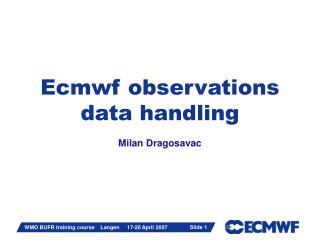
RAM local bus (32-bit) 32-bit PCI Bridge 32-bit PCI bus Hard drive Video ISA bridge PCI Slot ISA Slot Computer Bus Architecture CPU • 16-bit
15 16 31 0 0x00 0x04 0x08 0x0C 0x10 0x14 0x18 0x1C 0x20 0x24 0x28 0x2C 0x30 0x34 0x38 0x3C Vendor ID Device ID Status Command Class Code Rev Header Latency Cache BIST Base Address Registers Cardbus CIS Pointer Subsystem ID SubVendor ID Expansion ROM Base Address Reserved Reserved MaxLat MinGnt Int Pin Int Line PCI bus 33 MHz, 32-bit, address lines and data lines are shared • Memory (where cards live) • IO (chip connection) • Configuration • Bios on bootup • Each slot on the PCI bus has the configuration registers shown at the right.
1 2 3 4 The PCI bus • Wide Industry Support • Plug and Play capability • Thousands of software products • 32-bit data transfers at 33 MHz (132 Mbytes/sec) • PCI is a de facto standard • Automatic Resource Allocation • BIOS will normally "lock" the "PCI IRQ and DMA Settings" • PCI IRQ and DMA Settings can also be set manually But limited slots….
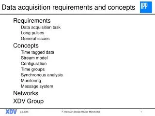
Full Size 6U Peripheral Sizes in PCI and CompactPCI PXI/CompactPCI PCI Half Size PCI boards can be redesigned to fit in PXI/CompactPCI with littleor no electrical changes. 3U • Eurocard Packaging Proven over decades of use in industrial applications (VME, VXI, etc.) Defined by IEEE 1101 Standard
1 2 3 4 1 2 3 4 5 6 7 8 PC Motherboard = Controller + Backplane PC Motherboard with 4 PCI slots CompactPCI 8-slotBackplane CompactPCI EmbeddedController
Star Trigger 10 MHz CLK Local Bus Trigger Bus Electrical Extensions : System Controller Peripheral Peripheral Peripheral Star Trigger Controller 132 Mb/s, 33 MHz, 32-bit Computer Bus • Integrated 8 Trigger Lines, 10 MHz reference clock, Star Trigger Bus • Local Bus between adjacent slots 13 lines
Mechanical Extensions Mandatory Active Cooling • System-level environmental specificationsfor EMC, shock, vibration, and humidity • Defined embedded controller location