Data Translation, Inc. Basics of Data Acquisition
540 likes | 755 Vues
Data Translation, Inc. Basics of Data Acquisition. Typical data acquisition applications . Physiological studies Environmental studies (temperature, etc.) Materials testing Medical research Quality control and testing. Typical data acquisition applications.

Data Translation, Inc. Basics of Data Acquisition
E N D
Presentation Transcript
Data Translation, Inc. Basics of Data Acquisition
Typical data acquisition applications • Physiological studies • Environmental studies (temperature, etc.) • Materials testing • Medical research • Quality control and testing
Typical data acquisition applications • Strain, pressure, temperature and vibration analysis • Fluid analysis • Manufacturing automation
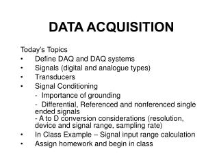
Components of a data acquisition systems • Analog to digital conversion (A/D) • Digital to analog conversion (D/A) • Digital input/output (DIO) • Pacer clock
Analog to Digital Conversion (A/D) • Once data has been converted from analog to digital, the digital information can then be processed by the computer, or transferred to memory
Digital to Analog Conversion (D/A) • D/A converters convert stored data back to a continuous signal (analog voltage) for display or control purposes • Output from the D/A converter can be used to drive external devices which require an analog input
Digital Input/Output (DIO) • Used primarily for control purposes • Used to transmit data between the host processor and an external digital device that expects to receive 1’s and 0’s
Pacer Clock • Used to initiate repetitive data conversions • Used to control the sampling rate of conversions
What is analog? • Analog signals are “continuous” signals • Represented by continuously changing physical quantities • Level of signal can be increased or decreased indefinitely • Ex. temperature, pressure, strain, voltage
What is digital? • Digital signals are “discrete” signals • Represented by separate, individual units • Units are represented by “bits” (binary digit) • Bits are represented by one of two possible states: on/off, true/false, 1/0
What is data acquisition? • A method of acquiring an analog signal and converting (digitizing) it into a binary code which can be manipulated by a computer Analog Signal Computer Analysis
A/D Interface • Converts analog data into digital data which can be processed • Typical components: • Multiplexers • Amplifiers • Sample and hold circuits • A/D converters
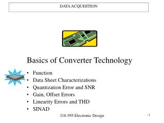
A/D Converter Functions • Input and output (I/O) • Analog input is converted into a digital number, by comparing the voltage with its position within the Full Scale Range • With an n-bit A/D converter the number of output levels equals 2n – e.g. 12-bit converter = 212 = 4096
Full Scale Range (FSR) • Full scale range refers to the largest voltage range which can be input into the A/D converter
Range • Range is an input span for an A/D and D/A system • Typical ranges are based on available sensors • Uni-polar (positive) • 0 to 5 volts • 0 to 10 volts • Bipolar • -5 to +5 volts • -10 to +10 volts
Full scale range examples +10v +1.25v +10v 0v -10v -1.25v FSR = 10v FSR = 20v FSR = 2.5v
Input/Output Digital Analog (101110010011)
Resolution • Resolution determines the smallest change that can be detected • Specified in bits. Determines number of output levels, or steps • 8 bits = 256 steps • 10 bits = 1024 steps • 12 bits = 4096 steps • 16 bits = 65,536 steps
Typical Resolutions • 8-bit – common for image capture • 10-bit – general analog acquisition • 12-bit – general analog acquisition • 16-bit – precision analog acquisition • 24-bit – high-accuracy analog acquisition
Output Levels/Resolution Example 1-bit A/D Converter +10v 1 0 0v
Output Levels/Resolution Example 2-bit A/D Converter +10v 11 10 01 00 0v
Output Levels/Resolution Example 4-bit A/D Converter +10v 1111 1110 1101 1100 1011 1010 1001 1000 0111 0110 0101 0100 0011 0010 0v 0001 0000
Output Levels/Resolution Example 12-bit A/D Converter +10v 1111 1111 1111 4096 Output Levels 0v 0000 0000 0000
Output Levels/Resolution Example 16-bit A/D Converter +10v 1111 1111 1111 65,536 Output Levels 0v 0000 0000 0000
LSB • LSB stands for “least significant bit” • An LSB represents the smallest change that can be resolved by the A/D converter • An LSB carries the smallest value or weight • An LSB is the rightmost bit • LSB = Full Scale Range (FSR) ÷ 2n
What affects conversion speed? • A/D converter only • A/D converter and related circuitry • A/D system and host
Acquisition time • The time required to perform a complete conversion from the analog signal to digital • The time required after receipt of “start digitizing” command until the A/D converter has finished digitizing
Settling time • Time it takes to switch to a new channel • Each time a user switches between channels, there is a delay, referred to as settling time
Throughput rate • The inverse of A/D conversion time + acquisition time • Measured in Hertz (Hz), which means the number of conversions per second • The maximum rate at which the data conversion system can operate, while maintaining a specific accuracy
Throughput • Acquisition System • The acquisition system determines the maximum throughput possible • The entire system (host, disk, A/D board, and program) determines the practical throughput
Throughput • Throughput is specified as an aggregate of all channels • A/D runs at a constant rate • Number of channels determines throughput per channel • The host computer and software must be able to service the A/D board before the next conversion is complete
Speeding up throughput rate • Overlap mode - while one sample is in Sample and Hold circuitry, the next is read into the multiplexer • Throughput equals the greater of conversion time OR acquisition time, plus any time needed for Sample and Hold switching
Getting signals into the computer • Transducers convert physical variables into electrical outputs • An input transducer (sensor) then supplies its output to signal conditioning circuitry (on a Screw Terminal Panel) • Signal conditioning circuitry prepares for interfacing with the PC
Amplification • The output of a sensor usually requires amplification • Apply gain
Gain • A scale (multiplying) factor which increases an input signal to better utilize the range of the A/D converter
Gain • Gain is the amplification applied to a signal to bring it to the range of the A/D system • High Level Gains (PGH) for high level signals – 1, 2, 4, 8 • Low Level Gains (PGL) for low level signals – 1, 10, 100, 500
5 volts 0 volts Selecting Gain and Range User Input Selected Range (uni-polar) 10 volts 0 volts Only 50% of the available A/D range is used.
5 volts 0 volts Selecting Gain and Range User Input Selected Range (bipolar) +10 volts 0 volts -10 volts Only 25% of the available A/D range is used.
0.25 v -0.25 v Selecting Gain and Range User Input Selected Range (bipolar) +10 volts Gain Amp 10 0 volts -10 volts Only 25% of the available A/D range is used.
Selecting Gain and Range User Input Selected Range (bipolar) 10 volts 1 volt 0 volts 0 volts -10 volts Using this range only utilizes 1/20th of the range. This would allow the input to be divided into 205 increments.
Selecting Gain and Range User Input Selected Range (uni-polar) 1.25 volts 1 volt 0 volts 0 volts Using this range utilizes 8/10ths of the range. This would allow the input to be divided into 3277 increments.
Selecting the Best Gain & Range • Analog input and output boards are generally designed to interface to the majority of sensors that are available • The ranges used on I/O boards may not always be appropriate for every application
Selecting the Best Gain & Range • To get the highest degree of accuracy possible out of an I/O board – try to utilize as much of the available range as possible • Use internal or external gain selection
Selecting the Best Gain & Range • Determine the maximum range that the input signal will use • Determine if the signal is uni-polar (above zero) or bipolar (above and below zero) • Evaluate the available gain and range combinations to select the most appropriate product
PGL Range/Gain Combinations Uni-Polar and PGL Example
PGL Range/Gain Combinations Bipolar and PGL Example
PGL Range/Gain Combinations Uni-Polar and PGH Example
PGL Range/Gain Combinations Bipolar and PGH Example
Methods of Transferring Data to Memory • Programmed input/output (PIO) – this is older technology and is slow • Polled I/O • Interrupts (shared and not shared) • Direct memory access (DMA)
Polled I/O • Data transfer is controlled by the CPU • CPU monitors the Data Ready bit of the A/D converter • When data is ready, the CPU reads it, then transfers it to memory • Very slow