Last Time
Last Time. Transformations Homogeneous coordinates Directions Rotation Geometry 101 – Points, edges, triangles/polygons Homework 3 due Oct 12 in class. Today. Viewing Transformations Describing Cameras and Views. Graphics Pipeline.


Last Time
E N D
Presentation Transcript
Last Time • Transformations • Homogeneous coordinates • Directions • Rotation • Geometry 101 – Points, edges, triangles/polygons • Homework 3 due Oct 12 in class © University of Wisconsin, CS559 Fall 2004
Today • Viewing Transformations • Describing Cameras and Views © University of Wisconsin, CS559 Fall 2004
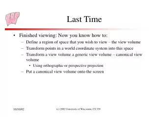
Graphics Pipeline • Graphics hardware employs a sequence of coordinate systems • The location of the geometry is expressed in each coordinate system in turn, and modified along the way • The movement of geometry through these spaces is considered a pipeline Local Coordinate Space World Coordinate Space View Space Canonical View Volume Display Space © University of Wisconsin, CS559 Fall 2004
Local Coordinate Space • It is easiest to define individual objects in a local coordinate system • For instance, a cube is easiest to define with faces parallel to the coordinate axes • Key idea: Object instantiation • Define an object in a local coordinate system • Use it multiple times by copying it and transforming it into the global system • This is the only effective way to have libraries of 3D objects © University of Wisconsin, CS559 Fall 2004
World Coordinate System • Everything in the world is transformed into one coordinate system - the world coordinate system • It has an origin, and three coordinate directions, x, y, and z • Lighting is defined in this space • The locations, brightness’ and types of lights • The camera is defined with respect to this space • Some higher level operations, such as advanced visibility computations, can be done here © University of Wisconsin, CS559 Fall 2004
View Space • Define a coordinate system based on the eye and image plane – the camera • The eye is the center of projection, like the aperture in a camera • The image plane is the orientation of the plane on which the image should “appear,” like the film plane of a camera • Some camera parameters are easiest to define in this space • Focal length, image size • Relative depth is captured by a single number in this space • The “normal to image plane” coordinate © University of Wisconsin, CS559 Fall 2004
Canonical View Volume • Canonical View Space: A cube, with the origin at the center, the viewer looking down –z, x to the right, and y up • Canonical View Volume is the cube: [-1,1]×[-1,1]×[-1,1] • Variants (later) with viewer looking down +z and z from 0-1 • Only things that end up inside the canonical volume can appear in the window • Tasks: Parallel sides and unit dimensions make many operations easier • Clipping – decide what is in the window • Rasterization - decide which pixels are covered • Hidden surface removal - decide what is in front • Shading - decide what color things are © University of Wisconsin, CS559 Fall 2004
Window Space • Window Space: Origin in one corner of the “window” on the screen, x and y match screen x and y • Windows appear somewhere on the screen • Typically you want the thing you are drawing to appear in your window • But you may have no control over where the window appears • You want to be able to work in a standard coordinate system – your code should not depend on where the window is • You target Window Space, and the windowing system takes care of putting it on the screen © University of Wisconsin, CS559 Fall 2004
Canonical Window Transform • Problem: Transform the Canonical View Volume into Window Space (real screen coordinates) • Drop the depth coordinate and translate • The graphics hardware and windowing system typically take care of this – but we’ll do the math to get you warmed up • The windowing system adds one final transformation to get your window on the screen in the right place © University of Wisconsin, CS559 Fall 2004
Canonical Window Transform • Typically, windows are specified by a corner, width and height • Corner expressed in terms of screen location • This representation can be converted to (xmin,ymin) and (xmax,ymax) • We want to map points in Canonical View Space into the window • Canonical View Space goes from (-1,-1,-1) to (1,1,1) • Lets say we want to leave z unchanged • What basic transformations will be involved in the total transformation from 3D screen to window coordinates? © University of Wisconsin, CS559 Fall 2004
Canonical Window Transform (1,1) (xmax,ymax) (xmin,ymin) (-1,-1) © University of Wisconsin, CS559 Fall 2004
Canonical Window Transform (1,1) (xmax,ymax) (xmin,ymin) (-1,-1) © University of Wisconsin, CS559 Fall 2004
Canonical Window Transform • You almost never have to worry about the canonical to window transform • In OpenGL, you tell it which part of your window to draw in – relative to the window’s coordinates • That is, you tell it where to put the canonical view volume • You must do this whenever the window changes size • Window (not the screen) has origin at bottom left • glViewport(minx, miny, maxx, maxy) • Typically: glViewport(0, 0, width, height)fills the entire window with the image • Why might you not fill the entire window? • The textbook derives a different transform, but the same idea © University of Wisconsin, CS559 Fall 2004
View Volumes • Only stuff inside the Canonical View Volume gets drawn • The window is of finite size, and we can only store a finite number of pixels • We can only store a discrete, finite range of depths • Like color, only have a fixed number of bits at each pixel • Points too close or too far away will not be drawn • But, it is inconvenient to model the world as a unit box • A view volume is the region of space we wish to transform into the Canonical View Volume for drawing • Only stuff inside the view volume gets drawn • Describing the view volume is a major part of defining the view © University of Wisconsin, CS559 Fall 2004
Orthographic Projection • Orthographic projection projects all the points in the world along parallel lines onto the image plane • Projection lines are perpendicular to the image plane • Like a camera with infinite focal length • The result is that parallel lines in the world project to parallel lines in the image, and ratios of lengths are preserved • This is important in some applications, like medical imaging and some computer aided design tasks © University of Wisconsin, CS559 Fall 2004
Orthographic View Space • View Space:a coordinate system with the viewer looking in the –z direction, with x horizontal to the right and y up • A right-handed coordinate system! All ours will be • The view volume is a rectilinear box for orthographic projection • The view volume has: • a near plane at z=n • a far plane at z=f , (f < n) • a left plane at x=l • a right plane at x=r, (r>l) • a top plane at y=t • and a bottom plane at y=b, (b<t) y (l,t,f) z x (r,b,n) © University of Wisconsin, CS559 Fall 2004
Rendering the Volume • To find out where points end up on the screen, we must transform View Space into Canonical View Space • We know how to draw Canonical View Space on the screen • This transformation is “projection” • The mapping looks similar to the one for Canonical to Window … © University of Wisconsin, CS559 Fall 2004
Orthographic Projection Matrix(Orthographic View to Canonical Matrix) © University of Wisconsin, CS559 Fall 2004
Defining Cameras • View Space is the camera’s local coordinates • The camera is in some location • The camera is looking in some direction • It is tilted in some orientation • It is inconvenient to model everything in terms of View Space • Biggest problem is that the camera might be moving – we don’t want to have to explicitly move every object too • We specify the camera, and hence View Space, with respect to World Space • How can we specify the camera? © University of Wisconsin, CS559 Fall 2004
Specifying a View • The location of View Space with respect to World Space • A point in World Space for the origin of View Space, (ex,ey,ez) • The direction in which we are looking: gaze direction • Specified as a vector: (gx,gy,gz) • This vector will be normal to the image plane • A direction that we want to appearup in the image • (upx,upy,upz), this vector does not have to be perpendicular to g • We also need the size of the view volume – l,r,t,b,n,f • Specified with respect to the eye and image plane, not the world © University of Wisconsin, CS559 Fall 2004
General Orthographic Subtle point: it doesn’t precisely matter where we put the image plane e image plane g t,n t,f y b,n (0,0) x b,f © University of Wisconsin, CS559 Fall 2004
Getting there… • We wish to end up in View Space, so we need a coordinate system with: • A vector toward the viewer, View Space z • A vector pointing right in the image plane, View Space x • A vector pointing up in the image plane, View Space y • The origin at the eye, View Space (0,0,0) • We must: • Say what each of these vectors are in World Space • Transform points from the World Space into View Space • We can then apply the orthographic projection to get to Canonical View Space, and so on © University of Wisconsin, CS559 Fall 2004
View Space in World Space • Given our camera definition, in World Space: • Where is the origin of view space? It will transform into (0,0,0)view • What is the normal to the view plane, w? It will become zview • How do we find the right vector, u? It will become xview • How do we find the up vector, v? It will become yview • Given these points, how do we do the transformation? © University of Wisconsin, CS559 Fall 2004
View Space • The origin is at the eye: (ex,ey,ez) • The normal vector is the normalized viewing direction: • We know which way up should be, and we know we have a right handed system, so u=up×w, normalized: • We have two vectors in a right handed system, so to get the third: v=w×u © University of Wisconsin, CS559 Fall 2004
World to View • We must translate so the origin is at (ex,ey,ez) • To complete the transformation we need to do a rotation • After this rotation: • The direction u in world space should be the direction (1,0,0) in view space • The vector v should be (0,1,0) • The vector w should be (0,0,1) • The matrix that does the rotation is: • It’s a “change of basis” matrix © University of Wisconsin, CS559 Fall 2004
All Together • We apply a translation and then a rotation, so the result is: • And to go all the way from world to screen: © University of Wisconsin, CS559 Fall 2004
OpenGL and Transformations • OpenGL internally stores two matrices that control viewing of the scene • The GL_MODELVIEW matrix is intended to capture all the transformations up to view space • The GL_PROJECTION matrix captures the view to canonical conversion • You also specify the mapping from the canonical view volume into window space • Directly through a glViewport function call • Matrix calls, such as glRotate, multiply some matrix M onto the current matrix C, resulting in CM • Set view transformation first, then set transformations from local to world space – last one set is first one applied • This is the convenient way for modeling, as we will see © University of Wisconsin, CS559 Fall 2004
OpenGL Camera • The default OpenGL image plane has u aligned with the x axis, v aligned with y, and n aligned with z • Means the default camera looks along the negative z axis • Makes it easy to do 2D drawing (no need for any view transformation) • glOrtho(…) sets the view->canonical matrix • Modifies the GL_PROJECTION matrix • gluLookAt(…) sets the world->view matrix • Takes an image center point, a point along the viewing direction and an up vector • Multiplies a world->view matrix onto the current GL_MODELVIEW matrix • You could do this yourself, using glMultMatrix(…) with the matrix from the previous slides © University of Wisconsin, CS559 Fall 2004
Typical Usage • GLU functions, such as gluLookAt(…), are not part of the core OpenGL library • They can be implemented with other core OpenGL commands • For example, gluLookAt(…) uses glMultMatrix(…) with the matrix from the previous slides • They are not dependent on a particular graphics card glMatrixMode(GL_PROJECTION); glLoadIdentity(); glOrtho(l, r, b, t, n, f); glMatrixMode(GL_MODELVIEW); glLoadIdentity(); gluLookAt(ex,ey,ez,cx,cy,cx,ux,uy,uz); © University of Wisconsin, CS559 Fall 2004
Left vs Right Handed View Space • You can define u as right, v as up, and n as toward the viewer: a right handed system uv=w • Advantage: Standard mathematical way of doing things • You can also define u as right, v as up and n as into the scene: a left handed system vu=w • Advantage: Bigger n values mean points are further away • OpenGL is right handed • Many older systems, notably the Renderman standard developed by Pixar, are left handed © University of Wisconsin, CS559 Fall 2004