
Pyrotechnic Shock Response
E N D
Presentation Transcript
Stage Separation Ground Test • Linear Shaped Charge • But fire and smoke would not occur in near-vacuum of space • Plasma jet would occur instead
Space Shuttle, Solid Rocket Booster, Frangible Nuts Frangible Nut Aft Skirt Foot Blast Container Aft Skirt Foot Hold Down Post Stud 4 Hold Down Post Assemblies per Each SRB
Delta IV Heavy Launch The following video shows a Delta IV Heavy launch, with attention given to pyrotechnic events. Click on the box on the next slide.
Pyrotechnic Shock Fields • Near Field - near source – shock is dominated by high-frequency wave motion • Mid Field - shock is composed of both wave motion and structural modes • Far Field - lower frequency response from structural modes Avoid mounting avionics component near pyrotechnic device!
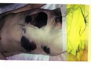
Pyrotechnic Shock Failures Crystal oscillators can shatter. Large components such as DC-DC converters can detached from circuit boards.
Shock Isolation, Elastomeric Isolated avionics component, SCUD-B missile. Public display in Huntsville, Alabama, May 15, 2010 The isolators break metal-to-metal contact Isolator Bushing
Shock Isolation, Wire Rope NASA/JPL Mars Science Laboratory Sensor Support Electronics mounted on vibration isolators
Pyrotechnic Events • Avionics components must be designed and tested to withstand pyrotechnic shock from: • Separation Events • Strap-on Boosters • Stage separation • Fairing Separation • Payload Separation • Ignition Events • Solid Motor • Liquid Engine
Frangible Joint • The key components of a Frangible Joint: • Mild Detonating Fuse (MDF) • Explosive confinement tube • Separable structural element • Initiation manifolds • Attachment hardware
Sample SRS Specification Frangible Joint, 26.25 grain/ft, Source Shock SRS Q=10 Used for design and test purposes
Pyrotechnic Shock Ramps Measured pyrotechnic shock are expected to have a ramp between 6 and 12 dB/octave
Sample Rate & Aliasing • For measuring pyrotechnic shock energy . . . • Sample rate should be at least 10X the maximum SRS frequency • Example: Sample Rate > 100 KHz for SRS up to 10 KHz • Rule-of-thumb: At least ten points are needed to represent one period of a sine function in the time domain • Analog anti-aliasing filter is vital, with cut-off frequency below the Nyquist frequency • Review Webinar 10 for further details
Flight Accelerometer Data, Re-entry Vehicle Separation Event Source: Linear Shaped Charge. Filename: rv_separation.dat Measurement location was near-field.
Apply rv_separation.dat as base input to SDOF (fn=700 Hz, Q=10)
Flight Accelerometer Data, SDOF Response Absolute Peak is 661 G.
Flight Accelerometer Data, SDOF Response (cont) Absolute Peak is 0.013 inch
Flight Accelerometer Data SRS (700 Hz, 660 G)
Flight Accelerometer Data SRS (cont) Peak pseudo velocity is 500 in/sec Severe!
Historical Velocity Severity Threshold • For electronic equipment . . . • An empirical rule-of-thumb in MIL-STD-810E states that a shock response spectrum is considered severe only if one of its components exceeds the level • Threshold = [ 0.8 (G/Hz) * Natural Frequency (Hz) ] • For example, the severity threshold at 100 Hz would be 80 G • This rule is effectively a velocity criterion. • MIL-STD-810E states that it is based on unpublished observations that military-quality equipment does not tend to exhibit shock failures below a shock response spectrum velocity of 100 inches/sec (254 cm/sec) • The above equation actually corresponds to 50 inches/sec • It thus has a built-in 6 dB margin of conservatism