Download
1 / 16
160 likes | 289 Vues
Progress Report: Alloy C-103 Behavior in High Vacuum August 27, 2012. N. Jacobson, J. Horwath , D. Humphrey* NASA Glenn Research Center *ZIN Technologies/NASA GRC Group. Alloy C-103. No oxygen. P(O 2 ) = 1 x 10 -6 bar.

E N D
Progress Report: Alloy C-103 Behavior in High VacuumAugust 27, 2012 N. Jacobson, J. Horwath, D. Humphrey* NASA Glenn Research Center *ZIN Technologies/NASA GRC Group
Alloy C-103 No oxygen P(O2) = 1 x 10⁻⁶ bar Behavior very sensitive to trace amounts of oxygen. Thermochemical modeling T = 1450C: ----------------------------------------------------------------------------------------------
Oxygen Active Metals at 1450C • Calculate minimum P(O2) to form oxide • Zr, Hf • Zr + O2(g) = ZrO2(s) P(O2) = 2.8 x 10⁻²⁴ bar • Hf+ O2(g) = HfO2(s) P(O2) = 3.8 x 10⁻²⁵ bar • Nb • Nb + 3/2 O2(g) = Nb2O5(s) P(O2) = 7.3 x 10⁻¹⁵ bar
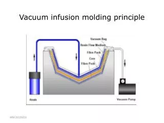
Task to Support FIELDS Project • Evaluate behavior of candidate alloys in high vacuum with thermogravimetric analysis • Use heat schedule provided by SSL/UCB • All vacuum has some amount of oxygen • Control this with a getter • Characterize microstructure of post-exposure samples • Field emission scanning electron microscopy (FE-SEM) • X-ray diffraction (XRD)—in progress • Characterize optical properties of post-exposure samples (S. Miller)
Hot Zone and Placement of Getter (Zr foil) 1. No getter—just W heat shields and W element. 2. Zr foil on top of bottom elements. 3. Zr foil on thermocouple, adjacent to sample.
C-103 080112 No GetterPost Exposure to UCB SSL Heat Schedule Nb Hf All images taken using a Hitachi S4700, images with red at the bottom were taken off EDS computer. All Images used for EDS scans are BSE BSE Image Hf Hf Nb
C-103 072312 Getter at BottomPost Exposure to UCB SSL Heat Schedule
Alloy C-103 072312 Getter at BottomPost Exposure to UCB SSL Heat Schedule Nb Hf Hf Nb BSE image; Corresponding SE image is on previous slide
C-103 080812 Getter on ThermocouplePost Exposure to UCB SSL Heat Schedule Hf BSE Image Hf Hf
Conclusions to Date C-103 consistently gains a few percent of its weight under these conditions Very sensitive to oxygen content in vacuum Appropriate placement of getter minimizers this weight gain Mechanism of weight gain appears to be related to Hf in alloy Changes in optical properties to be measured