Fast and Robust Edge-Based Localization Using Vision in Sony Four-Legged Robots
190 likes | 307 Vues
This project showcases a vision-based localization method for robots competing in the Sony Four-Legged Robot League. By employing a grid-based vision approach, the robot can determine its position by analyzing horizontal and vertical scan lines, identifying field markings, and utilizing Monte Carlo techniques for self-localization. The algorithm is designed to be fast and robust, allowing the robot to adapt to changing environments and lighting conditions. Various experimentations validate the precision of line-based localization while minimizing reliance on color segmentation, enhancing navigation autonomy.

Fast and Robust Edge-Based Localization Using Vision in Sony Four-Legged Robots
E N D
Presentation Transcript
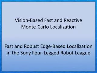
Vision-Based Fast and Reactive Monte-Carlo Localization Fast and Robust Edge-Based Localization in the Sony Four-Legged Robot League
http://www.youtube.com/watch?v=924_f2otWi4 http://www.youtube.com/watch?v=so9axknlftk
Grid-Based Vision • Horizontal line is determined by reading the pitch, yaw, and roll of the camera • Scan line spacing is used to speed up runtime scans • Those lines near or above the horizon are spaced close together for finer detail • Those lines well below the horizon are typically large and can be spaced further
Grid-Based Vision • Simple pattern recognition • Flags are determined by using the U- and V-channels • First three charts are examples of how the pattern is stored • The final image is a 3D representation of the pattern using the U-channel height map. Follows the same pattern for the U-Channel of the first chart
Grid-Based Vision • Goal and the field • Border and the field • Field lines and field • Top down evaluation to determine a pixel of interest
Self-localization • Monte Carlo Method • Define a domain of possible inputs. • Generate inputs randomly from the domain. • Perform a deterministic computation using the inputs. • Aggregate the results of the individual computations into the final result.
Self-localization • Motion Model • A prediction of where the robot will be given sensory data • Unexpected results can upset the model; being pushed or kidnapped • Observation Model • Uses visual landmarks to determine location • Susceptible to noise in the image • Calculated samples that are position correctly will receive a higher probability that that is the actual position of the robot next iteration • A maximum threshold is put into place to ensure probabilities don’t change drastically
Line-based Localization • 2nd look at identifying lines • Horizontal (left-right) scan lines are used along side Vertical (top-down) scan lines • This is a more desired method to perfect since actual soccer fields only use field lines and goals.
Line-based Localization • Once a pixel is identified a distance can interpolate the distance of that pixel • Depends upon the pose of the body; height, pitch, yaw, roll
Line-based Localization • Experiment used to determine accuracy of line-based localization • A ‘tale’ is constructed from paper so that the laser fires over the goals but intersects the paper tube sticking in the air.
Line-based Localization The AIBO attempts to localize itself while it is remotely driven around the field. Each line represents the distance from where the AIBO thought it was to where the laser detected it was. The AIBO is given instructions to move to a target location and stop. A line is then drawn from where the robot thought it was to where the laser determined the position. Only stop positions where recorded.
Questions The goals take up a small a percentage of the perimeter of the field. Also, it cannot be guaranteed that you will have line of sight to the goal and localization must be performed another way. The algorithm uses the field and border lines to localize the robot. Are the goals not large enough to be seen to help localize the robot the best? Resampling happens at each iteration. Samples are moved according to their probability. Samples with low probability will be removed and samples with high probability will receive more samples in that area. How resampling step is done, Do they use odometry value in their calculation? 100 samples for the guided approach and 200 samples for the walk-to-target excessive. What is number of particles?
Questions I believe this comes from the idea that we can localize ourselves using the borders, field lines, and goals. Typically these are high contrast points and pattern matching. In lower lighting white is still white and the field approaches black. If we can localize using only the field lines and boarders then we do not need to concern ourselves with color segmentation for localization. However, this doesn’t help find the ball or determine ownership of a goal. In the abstract the author claims that this approach is the first step towards independence of lighting conditions, how is this so? Or did you find any proof of this?