Download
1 / 1
10 likes | 146 Vues
IN-VIVO MR IMAGING OF MEDTRONIC ACTIVA DEEP BRAIN STIMULATION SYSTEM. Megan Cromer 1,2 and Sheryl Foster 1,2 1 Westmead Hospital 2 The University of Sydney, Australia. BACKGROUND

E N D
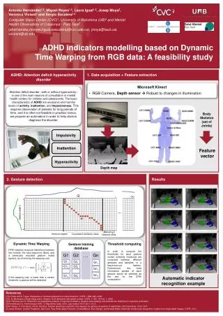
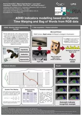
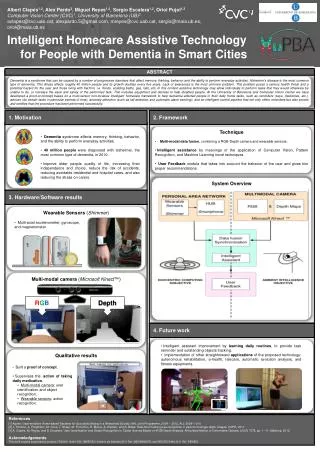
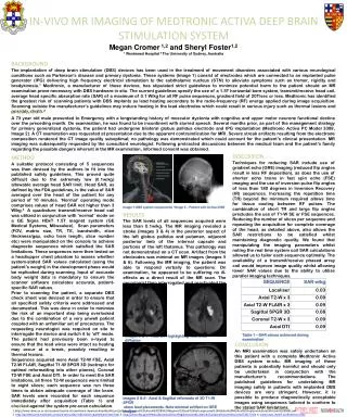
IN-VIVO MR IMAGING OF MEDTRONIC ACTIVA DEEP BRAIN STIMULATION SYSTEM Megan Cromer 1,2 and Sheryl Foster1,2 1Westmead Hospital 2 The University of Sydney, Australia BACKGROUND The implantation of deep brain stimulation (DBS) devices has been used in the treatment of movement disorders associated with various neurological conditions such as Parkinson’s disease and primary dystonia. These systems (Image 1) consist of electrodes which are connected to an implanted pulse generator (IPG) delivering high frequency electrical stimulation to the subthalamic nucleus (STN) to alleviate symptoms such as tremor, rigidity and bradykinesia.1 Medtronic, a manufacturer of these devices, has stipulated strict guidelines to minimize potential harm to the patient should an MR examination prove necessary with DBS hardware in situ. The current guidelines specify the use of a 1.5T horizontal bore system, transmit/receive head coil, average head specific absorption rate (SAR) of a maximum of 0.1 W/kg for all RF pulse sequences, gradient field of 20T/sec or less. Medtronic has identified the greatest risk of scanning patients with DBS implants as lead heating secondary to the radio-frequency (RF) energy applied during image acquisition. Scanning outside the manufacturer’s guidelines may induce heating in the lead electrodes which could result in serious injury such as thermal lesions and possibly, death.2 CASE STUDY A 73 year old male presented to Emergency with a longstanding history of muscular dystonia with cognitive and upper motor neurone functional decline over the preceding month. On examination, he was found to be incontinent with slurred speech. Several months prior, as part of the management strategy for primary generalized dystonia, the patient had undergone bilateral globuspallidus electrode and IPG implantation (Medtronic Activa PC Model 3389, Image 2). A CT examination was requested at presentation due to the apparent contraindication for MRI. Severe streak artifacts resulting from the electrode composition rendered the CT image quality suboptimal; no pathology was demonstrated which could account for the patient’s clinical presentation. MR imaging was subsequently requested by the consultant neurologist. Following protracted discussions between the medical team and the patient’s family regarding the possible dangers inherent in the MR examination, informed consent was obtained. DISCUSSION Techniques for reducing SAR include use of gradient echo (GRE) imaging (reduced flip angles result in less RF deposition), as does the use of shorter echo trains in fast spin echo (FSE) imaging and the use of inversion pulse flip angles of less than 180 degrees in Inversion Recovery (IR) sequences. Increasing the repetition time (TR) beyond the minimum required allows time for tissue cooling between RF pulses. The combination of short TR and large flip angles precludes the use of T1-W SE or FSE sequences. Reducing the number of slices per sequence and repeating the acquisition for complete coverage of the head, as detailed above, also allows the SAR restrictions to be satisfied whilst maintaining diagnostic quality. We found that manipulating the imaging parameters whilst noting the real time system coil SAR calculations allowed us to tailor each sequence optimally. The availability of a transmit/receive phased array coil would improve image quality whilst allowing lower SAR values due to the ability to utilise parallel imaging techniques. METHOD A suitable protocol consisting of 5 sequences was then devised by the authors to fit into the published safety guidelines. This proved quite difficult due to the extremely low (0.1w/kg) allowable average head SAR limit. Head SAR, as defined by the FDA guidelines, is the value of SAR averaged over the head of the patient for any period of 10 minutes. ‘Normal’ operating mode comprises values of head SAR not higher than 3 W/kg.3 A quadrature transmit/receive head coil was utilized in conjunction with ‘normal’ mode on a GE SignaHDxT 1.5T magnet system (GE Medical Systems, Milwaukee). Scan parameters (FOV, matrix size, TR, TE, bandwidth, slice thickness/gap, echo train length, slice number etc) were manipulated on the console to achieve diagnostic sequences which satisfied the SAR limitations. These sequences were then tested on a head/upper chest phantom to assess whether system-stated SAR values calculated (using the patient’s weight) in the development phase would be replicated during scanning. Input of accurate body weight data is mandatory to ensure the scanner software calculates accurate, patient-specific SAR values. Prior to scanning the patient, a separate DBS check sheet was devised in order to ensure that all specified safety criteria were addressed and documented. This was done in order to minimize the risk of an important step being overlooked due to the combination of a very unwell patient coupled with an unfamiliar set of procedures. The requesting neurologist was required on site to interrogate the device and switch it to ‘off’ mode. The patient had previously been x-rayed to ensure that the lead wires were intact as heating may occur at a break, possibly resulting in thermal lesions. Sequences acquired were Axial T2-W FSE, Axial T2-W FLAIR, Sagittal T1-W SPGR 3D (isotropic for optimal reformatting into other planes), Coronal T2-W FSE and Axial DTI. In order to meet the SAR limitations, all three T2-W sequences were limited to eight slices; each sequence was run three times to obtain adequate coverage of the brain. SAR levels were recorded for each sequence immediately after acquisition (Table 1) and checked against the system pre-scan calculation. Image 1-DBS system components4 Image 2 – Patient with Activa 3389 RESULTS The SAR levels of all sequences acquired were less than 0.1w/kg. The MR imaging revealed a stroke (Images 3 & 4) in the posterior aspect of the left globuspallidus and putamen, adjacent posterior limb of the internal capsule and portions of the left thalamus. This pathology was not demonstrated on a CT scan. Artifact from the electrodes was minimal on MR images (Images 5 & 6). Following the MR imaging, the patient was able to respond verbally to questions. On examination, he appeared to be suffering no ill-effects as a direct result of the MR scan. The neurologist then interrogated and reactivated the DBS device. B Table 1 – SAR values achieved during examination Images 3 & 4 - Axial DTI highlighting restricted diffusion CONCLUSION An MRI examination was safely undertaken on this patient with a complete Medtronic Activa DBS system in-situ. MR imaging of these patients is potentially harmful and should only be undertaken in conjunction with the manufacturer’s recommendations. The published guidelines for undertaking MR imaging safely in patients with implanted DBS devices are very stringent. However, it is possible to produce diagnostically acceptable images using sequences tailored to conform to the stated SAR limitations. Images 5 & 6 - Axial & Sagittal reformats of 3D T1-W SPGR show lead placements. Note minimal artifact on GRE images REFERENCES 1.http://www.ibme.ox.ac.uk/research/centre-of-excellence-inpersonalisedhealthcare/articles/Demand%20driven%20DBS%20Regimes%20and%20Autoregressive%20Hidden%20Markov%20ImplementationJSBrittain%20EMBC.pdf 2. http://professional.medtronic.com/pt/neuro/dbs-md/ind/mri-guidelines/index.htm3. http://www.fda.gov/MedicalDevices/DeviceRegulationandGuidance/GuidanceDocuments/ucm073817.htm4. www.news.medill.northwestern.edu