Fiber Optics Workshop
Fiber Optics Workshop. Dr Feng Zhou Department of Physics Indiana University of Pennsylvania. Biography. PhD in Optics in 1989 5 years postdoc in the UK (Strathclyde U., Glasgow U., and Imperial College) 5 years lecturer at Nanyang Technological U in Singapore (teaching & research);

Fiber Optics Workshop
E N D
Presentation Transcript
Fiber Optics Workshop Dr Feng Zhou Department of Physics Indiana University of Pennsylvania
Biography • PhD in Optics in 1989 • 5 years postdoc in the UK (Strathclyde U., Glasgow U., and Imperial College) • 5 years lecturer at Nanyang Technological U in Singapore (teaching & research); • 5 years of working experience with industry in the US (Corning Applied Tech, Nanovision, Phosistor, ESI Newwave Research). • Joined IUP since 2003, the new EO program supported by OP-TEC
Workshop Outline • This course consists of 2 sessions. This afternoon session is 4 hours (1-5 pm) and tomorrow morning is 1.5 hours (from 8:30-10:00 am). • This lecture is condensed from a 30 hr training course for Certified Fiber Optics Technician. • Sequence ->History -> basic concepts -> optical fibers -> light sources -> detectors -> other components such coupler and optical amplifier
Objectives • After completing this workshop, participants will be able to: • Define the basic technical differences between optical, wired, and wireless communications systems. • Discuss applications of optical, wired, and wireless communications systems. • Explain some of the factors that can impact optical, wired, and wireless communications systems.
The Textbook • We will cover all the content except the fiber sensors.
Fiber Optic Installation Standard • ANSI/NECA/FOA 301 • Written for installers • Defines installation in a “neat and workmanlike manner” • Covers premises and outside plant • Free online
Lennie Lightwave’s Guide http://www.lennielightwave.com
Session 1: Basics of Fiber Optics This session provides • A historical review of Fiber Optics development • Refractive index, total internal reflection • An understanding of the basics of optic fiber.
What is Fiber Optics • Transmitting communications signals using light over hair thin glass or plastic fibers • Concept over a century old • Technology used commercially for 25 years
History • Interest in the use of light as a carrier for information grew in the 1960's. • As Corning made the first low loss glass fiber in 1970 (<20dB/km), it became feasible to use optical fibers as a practical transmission medium. • The high loss was due to impurities. Charles Kao 2009 Nobel price • By 1980 world wide installation of fiber optic communication systems had been achieved. • By 1990, erbium doped fibers were used as optical amplifiers.
Future Trends • Fiber is already used in: • >90% of all long distance telephony and >50% of all local telephony; • Most CATV networks and LAN backbones; • Many video surveillance links. • Fiber is the least expensive, most reliable method for high speed and/or long distance communications • While we already transmit signals at GB/s speeds, we have only started to utilize the potential bandwidth of fiber.
Advantages of Fiber Optic Comm • What are the advantages?
Advantage 1 • Capacity - Optical fibers carry signals with much less energy loss than copper cable and with a much higher bandwidth. This means that fibers can carry more channels of information over longer distances and with fewer repeaters required. • Bandwidth: A measure of the maximum frequency by which light intensity can be modulated [MHz/km]. The greater the bandwidth, the greater the information carrying capacity .
Advantage 2 • Size and Weight - Optical fiber cables are much lighter and thinner than copper cables with the same bandwidth. This means that much less space is required in underground cabling ducts. Also they are easier for installation engineers to handle.
Advantage 3 • Security – • difficult to tap information; a great advantage for banks and security installations. • immune to Electromagnetic (EM) interference from radio signals, car ignition systems, lightning etc. They can be routed safely through explosive or flammable atmospheres.
Advantage 4 • Running Costs - The main consideration in choosing fiber when installing domestic cable TV networks is the electric bill. Although copper coaxial cable can handle the bandwidth requirement over the short distances of a housing scheme, a copper system consumes far more electrical power than fiber, simply to carry the signals.
Application Areas of Fiber Optics • Telecom - telephones and the Internet (capacity) • LANs - local area networks (weight/size) • CATV (cable TV) - for video, voice and Internet connections (low running cost) • Security - CCTV (closed circuit TV) and intrusion sensors (security) • Military - everywhere! (immune to EM & security)
Basic Fibre Optic System Electrical Signal In Transmitter FO cable plant Receiver Electrical Signal Out O/p Circuit Source Driver Detector FO cable plant Transmitter: uses laser or LED, etc to covert an electrical signal to an optical signal. Receiver: uses a photodiode to convert optical to electric signal. Physical plant: Fiber (SM or MM); Cable (application specific); Connectors; Splices; Panels; and Closures.
How to make glass fibers • Three methods: • MCVD • OVD • VAD
Consolidation • When deposition is complete, the tube with the soot is placed into a consolidation furnace. • During the consolidation process, the tube changes into a solid, dense, transparent glass blank which is called preform. • After the preform cools, it is ready for drawing. • Which part will be the cladding? The core?
Fiber Drawing Tower 1900-2500oC Diameter control buffer coating buffer coating 10-20 m/s
Video • How to make a preform • How to draw fiber from a preform
Optics - Reflection of Light • Consider the light strikes a flat mirror at the point P and is then reflected. • How do you describe the reflected beam?
Law of Reflection p surface normal • The surface normal is a line perpendicular to the surface at the point the light ray hits • The normal and the incident ray form the plane of incidence. reflecting surface plane of incidence Angle of incidence = angle of reflection • The incident ray, normal, and the reflected ray all lie in the incidence plane perpendicular to the reflecting surface.
Speed of Light In vacuum: • The speed of light c = 3x10⁸ m/s Light/Matter Interaction • Think about the speed of light in air, in water and in a solid, which speed is fastest? Which speed is slowest? Why?
Index of refraction, n • Index of refraction, a way to indicate the speed of light in a medium • n = c/v • n<1, ~ 1, or > 1? • Slow down the speed of light with a huge n?
Index of Refraction n • In vacuum, the speed is highest. c = 3x10⁸ m/s. • In traveling through all matter, the velocity is slower, depending on material properties.
Refractive Indices of Materials • ngas < nliquid < nsolid. • Higher refractive index means more dense of the material.
Light at a Boundary • “Different refractive indexes” form boundaries. • At a boundary, some light is reflected, some transmitted, and some absorbed • depending on material properties which form the boundary n1 n2
Law of refraction • How about the direction of the refracted light? • Amount of bending depends on refractive indexes n1, n2 of the two materials, as given by Snell’s law. n1sinq1 = n2sinq2
Two possible cases exist n1 Less dense Air n = 1.0 n1 More dense Glass n = 1.5 q1 q1 n1 < n2 n1 > n2 More dense n2 glass n = 1.5 Less dense n2 Air n = 1.0 q2 q2 When traveling from more dense to less dense medium, light is bent away from the normal. When traveling from less dense to more dense medium, light is bent toward the normal.
Total Internal Reflection (TIR) n2 = 1 q2 qc q1 n1 = 1.5 • From more dense to less dense medium, light is bend away from the normal => So q2 > q1. • What will it happen if we increase q1?
Critical angle • At the point when q2 = 90o, q1 has reached a value called the critical angle (q1 = qc ). n1sinqc = n2sin90o sinqc = n2/n1 qc = arcsin (n2/n1) = sin-1(n2/n1) • Once q1 >=qc, there is no transmitted ray and all the light energy is reflected. • This phenomenon is called Total Internal Reflection (TIR).
Examples –qc at Interfaces Ex 1: Given: n1 = 1.49for glass fiber core and n2=1.47 for the cladding. Find: critical angle qc Solution Ex 2: For a glass-air interface, n1 = 1.5, n2 = 1.0, and the critical angle is given by qc = sin–1 (1.0/1.5) ≈ 41.8°
Demonstrations of TIR • In the 1840s, people noticed that the light cold be guided in a jet of water flowing from a tank. • This is now known as total internal reflection (TIR). • Light propagates through fibers by the principle of TIR. • More TIR examples: • Light pipes • Right angle prisms
For TIR to Occur • The refractive index of the 1st medium is greater than the refractive index of the 2nd one. • e.g.., glass to air • The incident angle is large. • TIR causes 100% reflection (no energy loss). • In no other situation in nature, where light is reflected, does 100% reflection occur. So TIR is unique and very useful.
Optic Fiber • Is a dielectric waveguide. • Core refractive index is higher than the cladding refractive index. • Light is confined within the optic fiber by TIR.
Attenuation vs wavelength v1 O–Si–O bending mode; v13O–H stretching mode
Structure of an Optics Fiber • Core refractive index is higher than the surrounding material’s refractive index. • Light is confined within the optic fiber by Total Internal Reflection (TIR). • Core and cladding are both made of glasses of different refractive indexes and can not be separated.
Fiber Core/Cladding Sizes • Here are the three most widely used fiber types: • 50/125 microns; • 62.5/125 microns; • 8-10/125 microns. • The buffer has a diameter of 250 microns. • Human hair has a typical diameter of 75 microns.
Cross Section of a Bare Fiber Bare fiber
Cross Section of a Fiber Cable Fiber Cable
Metric Units • Fiber optics uses the metric systems as the standard form of measurement. • Several of the more common terms are: • Meter (m): 39.37 inches, or just slightly larger than a yard. • Kilometer (km): 1,000 meters (3,281 feet) or approximately 0.62 of a mile. • Micron (m): One millionth of a meter. • Nanometer (nm): One billionth of a meter.
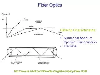
Numerical Aperture • Numerical Aperture is the “light gathering ability” • The numerical aperture is defined as NA = (n12 – n22) = sinqA • It is a measure of the light gathering power of the fiber. • Example: Calculate NA and the acceptance angle of a fiber with a core refractive index of 1.53 and cladding of 1.50.
About NA • It lies between 0 and 1. • A numerical aperture of 0 means that the fiber gathers no light (corresponding to qA = 0o). A numerical aperture of 1 means that the fiber gathers all the light that falls onto it (corresponding to qA = 90o).
The Fiber Loss - Decibel (dB) • A logarithmic unit describing the ratio of two powers. • dB = 10 log10 (Pout/Pin) • dB = 10 log10 (power remaining) Input power, Pin Output power, Pout Circuit • Used to measure losses (or attenuations).