Download
1 / 27
270 likes | 302 Vues
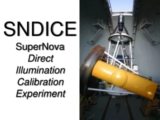
Installation of the SNDICE calibration instrument at CFHT in 2007 for precise illumination calibration. LED light source monitoring, design of test bench, and electronic control system are part of the project.

E N D
SNDICECalibration Instrumentalede Megacam • Installation au CFHT fin 2007 (durée > 1 an) • Collaborateurs : • P. Bailly, E. Barrelet, W. Bertoli, C. Evrard, J-F Huppert, C. Juramy (2006), H. Lebolo, K. Schahmaneche, R. Sefri, A. Vallereau, D. Vincent, • Coût total 125 k€
Revue SNDICE 13 Novembre 2006 Conseil scientifique 24 Novembre 2006 CSP 12 Décembre 2006
Illumination Directe source de LEDs calibrée(LPNHE2006-02) • Monitoring du telescope • Echantillonage de R() • Design simple
Mesures prévuessur le banc de test • LEDs : • Obtenir une lumière stable avec contrôle du courant et du photocourant dans photodiodes de contrôle • Relations entre tension, courant, température, et puissance lumineuse émise • Distribution spectrale • Distribution spatiale : Integral Radiometric Calibration • CLAP : • Mesure et amplification de signaux qq fA/cm2 • cross-calibration avec photodiode calibrée NIST, via la calibration des LEDs • Prototype d’une carte avec 8 voies (Janvier 2007)
Workpackages • Électronique de contrôle et acquisition • Asic • Tête de LEDs • Banc de calibration
Schéma du dispositif (Cooled Large Area Photodiode) (LEDs source)
Carte électronique principale Précision visée : < 1 ‰ DACs FPGA to computer • Sources de courant des LEDs : 20 DACs 12-bit, 20 switches, un temps de pose commun • Lecture du courant des photodiodes : LCA, multiplexeur,ADC 16-bit • Alimentations pour : DACs, ADCs, LCAs, polarisation des photodiodes • FPGA • Ethernet : XiLinks Virtex 4 pour la programmation du FPGA to LED source Mux ADC LCAs
SNDICE– LCA Photodiode refroidie(CLAP : Cooled Large Area Photodiode) • Mesure redondante • qq fA/cm2 refroidissement (Peltier) “grande” surface besoin d’un LCA (Low Current Amplifier)
SNDICE– LCA LCA : schéma
SNDICE– LCA ASIC(R&D SNAP) • préampli de courant • ampli de tension double gain
Specifications SNDICE– Tête de LEDs 1.LEDs module Design of the LEDs module as much for the test bench as for the installation on the telescope Requirements(although specifications are not precisely defined yet) : • Number of LED : between 20 and 24 (to cover spectral bandwidth from UV to NIR) • surface mount form factor LED with flat top • 1 control photodiode associated with every LED • could be edge-illuminated photodiode ? • Baffling against stray light • 1st mask to get rid of rim reflection so that we have an almost point-like light source • 2nd mask acting as a diaphragm to get a cone shape light with an angle of 3° • Constraints from climate and weather environnement at CFHT • Space requirements to stay outside telescope and camera field of view • Interface with telescope structure for fastening • Equipped with a sight system and tilt-and-swivel mechanism to adjust the optical axis toward the camera
Requirements SNDICE– Tête de LEDs • Fixation and positionning of the LEDs • our previous experience : home-made mechanical positionning, LED glued • better to use industrial electronic means and solder LED directly on an PCB ?
SNDICE– Banc de calibration • 1st step : test of LEDs and photodiodes to choose the right ones prototypes of LEDs module • 2nd step : calibrate the LEDs by using the NIST calibrated photodiode • The aim is to define a 3D map of the light field and measure light homogeneity for each LED within an useful area • we need to move either the light source or the light receiver relatively to each other with 3 degrees of freedom • The distance between source and receiver would range from 1m to 2.5m to get adequate illumination • 3rd step : calibrate the Hamamatsu photodiode with the then calibrated LEDs We need to increase the distance between source and receiver to lower illumination In order to come close to working conditions on the telescope, this distance should be around the focal plane distance of Megaprime (~13.5 m) extension of the optical bench • 4th step : design for the lay out of the calibrating system on the Megaprime instrument
Photodiodes SNDICE– Banc de calibration Black box(not drawn) 1 NIST calibrated photodiode (high illumination sensitivity) 1 Hamamatsu cooled photodiode (low illumination sensitivity) LEDs module Optical bench
Specifications SNDICE– Banc de calibration 2.Optical bench existing XY translation system ? Carriage guided by 4 rollers along aluminium profil motor driven by synchronous belt repeatability +/- 0.1 mm existing granit rail • Motorized translation along the optical axis (Z) scanning 1m to 2.5m from the LEDs module • precision : 0.5 mm (enough to be precise better than 0.1% related to the distance) • XY motorized translation system scanning an area around 20x20 cm² • precision : 0.5 mm • Tilt-and-swivel system to align LEDs and photodiodes • precision : fraction of milli radian • Black box • Feedthrough for power and signal cables • Opening on one side to « extend » the bench • up to 14m
Manpower 3.4 h*ans 2.4 h*ans 0.2 h*ans 2.9 h*ans Total = 8.9 h*ans
DICE Group Review Findings(Paris Nov 13, 2006 - K. Gilmore invited) • Photometric calibration is indeed a key issue of current and future wide field surveys • Quantify the scientific gain • Direct illumination with LEDs is a very appealing concept • Key features (stability and control, LED light emission properties, …) to be validated on test/calibration bench • Get results from «Dome illumination with a tunable laser » experiment at CTIO (C. Stubbs) • Cost estimate found ok - Technical team found strong • Problem with the leaving of C. Juramy in Jan 07 • Go forward: immediately - do test/calibration bench validation measurements - start discussing implementation with CFHT
Risques (1) • Accord du CFHT ? • Courrier au CFHT cet été • Une visioconférence fin Novembre • 23-11: CFHT prêt à collaborer à cette étude • Envoi d’un proposal au CFHT le 5-12-06 • Une visioconférence avant la fin de l’année • …
Risques (2) • Choix des leds • Mesures sur le banc test en cours • …
Risques (3) • Ressources • Budget réaliste • Manpower ITA , pas de problème • Départ de Claire Juramy fin Décembre • Mesure sur banc test • Analyse
Conclusions • Peu de problème , mais: • Encore beaucoup de mesures, de tests et de simulation à faire : MANPOWER côté physiciens • Si validé : calibration pour des expériences ultérieures (LSST, satellites,…)