Download
1 / 50
500 likes | 587 Vues
What is current?. A flow of electrons forced into motion by voltage is known as current. The atoms in good conductors such as copper wire have one or more free electrons of the outer ring constantly flying off. Current. Electrons from other nearby atoms fill in the holes.

E N D
What is current? • A flow of electrons forced into motion by voltage is known as current. • The atoms in good conductors such as copper wire have one or more free electrons of the outer ring constantly flying off.
Current • Electrons from other nearby atoms fill in the holes. • There are billions of electrons moving aimlessly in all directions, • all the time in conductors.
Current • When an emf (voltage) is impressed across a conductor it drives these free electrons away from the negative force toward the positive. • This action takes place at near the speed of light, 300,000,000 metres per second • although individual electrons do not move far they have a shunting effect.
Current • This is similar to a number of cars pulled up at traffic lights • when the last vehicle fails to stop and hits the second last vehicle • which in turn hits the third last vehicle...............
Current • The amount of current in a circuit is measured in amperes (amps). • Smaller units used in electronics are milli-amps mA (1 / 1,000th of an ampere) and micro-amps uA (1 / 1,000,000th of an ampere). • An ampere is the number of electrons going past a certain point in one second.
Current • The quantity of electrons used in determining an ampere is called "coulomb" • which one ampere is one coulomb per second. • A coulomb is 6,280,000,000,000,000,000 or 6.28 X 10 18 electrons. • This (a coulomb) is the unit of measuring electrical quantity or charge.
Current vs. Electron Flow • current flows from the positive to the negative terminal, • but electrons actually flow from the negative to the positive terminal. • In other words, current and electrons flow in opposite directions.
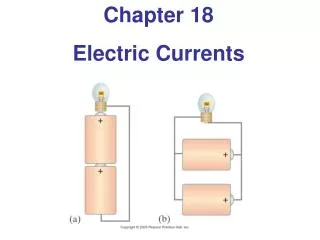
AC and DC Current • AC stands for alternating current, and DC for direct current. • In AC circuits the current regularly switches direction. • In DC circuits the current always flows in the same direction
AC and DC Current • Your home uses AC circuits at approximately 110 volts (larger appliances like dryers and electric stoves require 220 V AC). • The electrical outlets for higher voltage devices look different from the normal household outlet.
AC and DC Current • The Electricity and Power in Space activities involve DC circuits only, • using voltages ranging from 1.5 to 6 volts. • The International Space Station is powered by DC circuits at approximately 110 volts.
Voltage • Voltage should be more correctly called "potential difference". • Voltage is actually the electron moving force in electricity (emf) and • the potential difference is responsible for the pushing and pulling of electrons or electric current through a circuit.
Sources of electromotive force (EMF) or voltage • To produce a drift of electrons, or electric current, along a wire • it is necessary that there be a difference in "pressure" or potential between the two ends of the wire. • This potential difference can be produced by connecting a source of electrical potential to the ends of the wire.
EMF • There is an excess of electrons at the negative terminal of a battery and a deficiency of electrons at the positive terminal, due to chemical action. • Then it can be seen that a potential difference is the result of the difference in the number of electrons between the terminals.
EMF • The force or pressure due to a potential difference is termed e.m.f. or voltage. • An emf also exists between two objects whenever there is a difference in the number of free electrons per unit volume of the object.
EMF • If the two objects are both negative, current will flow from the more negatively charged to the less negatively charged when they are connected together. • There will also be an electron flow from a less positively charged object to a more positively charged object.
EMF • The electrostatic field, i.e. the strain of the electrons trying to reach a positive charge or from a more highly negative charge is emf or voltage. • It is expressed in units called volts, short for voltage. • A volt can be defined as the pressure required to force a current of one ampere through a resistance of one ohm.
EMF • To make this easier to visualise, • consider the water pressure (voltage) • required to pass a litre of water (current) • through a copper pipe of a certain small diameter (resistance).
EMF • Also try and visualise water going through other pipes of varying diameters (smaller to larger in size). • Either the water pressure required would vary or the volume delivered would vary, or both.
Electrical potential • 'Electrical potential' is a condition, which determines the direction of the flow of charge. • Let us consider the experiment outlined below to understand electrical potential
Electrical potential • Pipe A is connected to the container B through a stopcock. • The quantity of water in A is less than the quantity in B, but the level of water is higher than the level in B. • When the stopcock is opened, this water begins to flow from A to B, till the levels of water in both A and B are equal.
Electrical potential • The above observation, determines that it is not the quantity of water, but the level of water, which decides the direction of flow of water. • Here the water in 'A' is at a higher 'gravitational potential' and the water in 'B' is at a lower gravitational potential.
Electrical potential • It is the 'potential difference' that is responsible for the flow of water. • Similarly 'electrical potential' is the direction of the flow of charge.
voltage can be generated in many different ways • Chemical (batteries) e.g. dry cell 1.5V, wet cell storage about 2.1V • Electromagnetic (generators) • Thermal (heating junctions of dis-similar metals) • Piezoelectric (mechanical vibration of certain crystals) • Photoelectric (light sensitive cells)
Resistance • In the topic current we learnt that certain materials such as copper have many free electrons. • Other materials have fewer free electrons and substances such as glass have practically no free electron movement • therefore making good insulators.
Resistance • Between the extremes of good conductors such as silver, copper and • good insulators such as glass and rubber lay other conductors of reduced conducting ability, • they "resist" the flow of electrons hence the term resistance..
Resistance • The specific resistance of a conductor is the number of ohms in a 1' (305mm) long, 0.001" diameter round wire of that material. • Some examples on that basis are Silver = 9.75 ohms, Copper = 10.55 ohms, Nickel = 53.0 ohms and Nichrome = 660 ohms
Resistance • From this information we can deduce that for a voltage applied to a piece of Nichrome wire , • only around 10.55 / 660 = 0.016 of the amount of current will flow as opposed to the the current flowing in the same size copper wire.
Resistance • The unit of resistance is the ohm and 1 ohm is considered the resistance of round copper wire, 0.001" diameter, 0.88" (22.35 mm) long at 32 deg F (0 deg C).
Resistance in series and parallel • It follows if two such pieces of wire were connected end to end (in series) • then the resistance would be doubled, • on the other hand if they were placed side by side (in parallel) • then the resistance would be halved!
Resistance in series and parallel • This is a most important lesson about resistance. • Resistors in series add together as R1 + R2 + R3 + ..... • While resistors in parallel reduce by 1 / (1 / R1 + 1 / R2 + 1 / R3 + .....)
Resistance in series and parallel • Consider three resistors of 10, 22, and 47 ohms respectively. • Added in series we get 10 + 22 + 47 = 79 ohms. • While in parallel we would get 1 / (1 / 10 + 1 / 22 + 1 / 47) = 5.997 ohms.
Resistance and Power • Next we need to consider the power handling capability of our resistors. • Resistors which are deliberately designed to handle and radiate large amounts of power are • electric cooktops, ovens, radiators, electric jugs and toasters. • These are all made to take advantage of power handling capabilities of certain materials.
Resistance in series and parallel • From our topic on ohms law we learnt that P = I * I * R that is, • power equals the current squared times the resistance. • Consider our example above of the three resistors in series providing a total resistance of 79 ohms.
Resistance in series and parallel • If these resistors were placed across a 24 volt power supply then the amount of current flowing, from ohms law, is I = E / R = 24 / 79 = 0.304 amperes.
Resistance in series and parallel • Using any of our power formulas we determine that 0.304 amperes flowing through our 79 ohm resistance dissipates a combined 7.3 watts of power! • Worse, because our resistors are of unequal value the power distribution will be unequal with the greater dissipation in the largest resistor.
Resistance in series and parallel • It follows as a fundamental rule in using resistors in electronic circuits that the resistor must be able to comfortably handle the power it will dissipate. • A rule of thumb is to use a wattage rating of at least twice the expected dissipation.
Resistance in series and parallel • Common resistors in use in electronics today come in power ratings of 0.25W, 0.5W, 1W and 5W. • Other special types are available to order. • Because of precision manufacturing processes it is possible to obtain resistors in the lower wattage ratings which are quite close in tolerance of their designated values.
Resistance in series and parallel • Typical of this type are the .25W range which exhibit a tolerance of plus / minus 2% of the value. • Resistors come in a range of values • but the two most common are the E12 and E24 series.
Resistance in series and parallel • The E12 series comes in twelve values for every decade. • The E24 series comes in twenty four values per decade. • E12 series - 10, 12, 15, 18, 22, 27, 33, 39, 47, 56, 68, 82 • E24 series - 10, 11, 12, 13, 15, 16, 18, 20, 22, 24, 27, 30, 33, 36, 39, 43, 47, 51, 56, 62, 68, 75, 82, 91
Resistance in series and parallel • You will notice with the E12 values that each succeeding value falls within • the plus / minus 10% of the previous values. • This stems from the real old days when resistances were stated as within 20% tolerance (accuracy).
Resistance in series and parallel • Later values of plus / minus 5% tolerance led to the E24 range of resistance. • Quite common today are 2% tolerance metal films types but for general purpose use we tend to stick to • E12 values of resistance in either 1%, 2% or 5% tolerance.
Resistance in series and parallel • Cost is the determining factor and many retailers now stock the 2% range of resistance as a standard • to minimise stocking levels and also at reasonably low cost.
Resistance in series and parallel • As examples of say the "22" types (red - red) from the E12 series we get 0.22, 2.2, 22, 220, 2,200, 22,000, 220,000 and 2,200,000 or eight decades of resistors.