Download
1 / 22
230 likes | 588 Vues
"Materials for Solid Oxide Fuel Cells" G. Dezanneau Structures, Properties and Modelisation of Solids LaB. Ecole Centrale Paris. Outline of the talk. Team : "Materials for hydrogen technologies" Research activities Materials for Solid Oxide Fuel Cells

E N D
"Materials for Solid Oxide Fuel Cells" G. Dezanneau Structures, Properties and Modelisation of Solids LaB. Ecole Centrale Paris
Outline of the talk • Team : "Materials for hydrogen technologies" • Research activities Materials for Solid Oxide Fuel Cells • Objectives of research in Solid Oxide Fuel Cells • New electrolyte materials Conclusion
Guilhem Dezanneau CNRS researcher Animator of the team Grégory Geneste Professor assistant Ab initio modelling Michel Gramond Engineer Instrumentation and automation Christine Bogicevic CNRS Engineer Elaboration of materials Fabienne Karolak TechnicianECP Elaboration of materials Émile Bévillon Ph.D. student – ECP Ab initio Modelling of proton conductors Yanzhong Wang Ph.D. student – Chinese Scientific Comittee Study of new proton conductors Yang Hu Ph.D. – Chinese Scientific Comittees Study of new materials for fuel cells Marc-David Braida Ph.D. student - ECP Study of new proton conductors SPMS: Materials for hydrogen technologies " Materials for hydrogen technologies " • Materials for hydrogen technologies: - Solid Oxide Fuel Cells: anion / protonic conductors mixed (ion – electron) conductors for electrodes defects chemistry : experimental and theoretical approach from the elaboration till the test of button cells - Hydrogen storage - Hydrogen production : High temperature electrolysis & water Photolysis
Team "Materials for hydrogen technologies" • Research activities Materials for Solid Oxide Fuel Cells • Objectives of research in Solid Oxide Fuel Cells • New electrolyte materials Conclusion
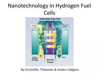
What is a fuel cell ? • Energy converter that transforms chemical energy from H2 (and O2) into electricity and heat • Can be seen as a “Continuous battery” • Runs as long as fuel and air (oxidant) are supplied H2 H2 + O2- H2O + 2e- H2O Interconnexion materials 2e- Anode O2- O2- O2- Cathode 2e- 1/2O2 + 2e- O2- O2 Air N2 • High efficiency (till 85% in a cogeneration mode) • Environmental friendly • Noise free and no site restriction
SOFCs: challenge H2 H2O Interconnexion materials H2 + O2- H2O + 2e- 2e- Anode O2- O2- O2- Cathode 2e- 1/2O2 + 2e- O2- O2 Air N2 Limitation : high working temperature ~ 900 – 1000 ºC High Cost (ceramics interconnexion materials) Accelerated materials ageing Research objective : working temperature (~ 600 – 800 ºC) Find a configuration with the same transport properties BUT at lower temperature Minimise Internal ohmic losses (Rcell = Relectrolyte + Relectrode)
Electrode-supported Fuel Cells SOFCs: challenge How to minimise internal losses ? Playing on geometry Electrolyte-supported Fuel Cells
SOFCs: challenge How to minimise internal losses ? Playing on geometry : thin electrolytes thin electrolyte deposition by screen-printing (1) Side view Top view Full Density (1350ºC) Crack free (1) A. Tarancon, A. Morata, Ph.D. theses, University of Barcelona
SOFCs: challenge How to minimise internal losses ? Playing on geometry : thin electrolytes thin electrolyte deposition by screen-printing (1) Playing on materials (1) A. Tarancon, A. Morata, Ph.D. theses, University of Barcelona
SOFCs: challenge How to minimise internal losses ? Playing on geometry: thin electrolytes thin electrolyte deposition by screen-printing (1) Playing on materials: New electrolyte materials • New anion conductors: La9.33+xSi6O26+3/2x • Proton conductors : La6-xMoO12-3/2x, BaSn1-xMxO3-d (2) Playing on materials : New electrode materials GdBaCo2O5.5+d cobaltite : a new electrode material(1, 3) (1) A. Tarancon, A. Morata, PhD theses, University of Barcelona (2) PhD theses of Y. Wang and M.D. Braida, SPMS Lab. (3) PhD Thesis of Y. Hu, SPMS Lab.
GBCO = GdBaCo2O5+δ [BaO] [CoO2] [GdOδ] [CoO2] [BaO] SOFCs: New electrode materials Mixed ion-electron conducting material • A very low value of R=0.3 .cm2 already reached at 625°C • Current work on Co substitution by Fe or Ni to improve electrical and chemical properties
SOFCs: challenge How to minimise internal losses ? Playing on geometry: thin electrolytes thin electrolyte deposition by screen-printing (1) Playing on materials: New electrolyte materials • New anion conductors: La9.33+xSi6O26+3/2x • Proton conductors : La6-xMoO12-3/2x, BaSn1-xMxO3-d (2) Playing on materials : New electrode materials GdBaCo2O5.5+d cobaltite : a new electrode material(3) (1) A. Tarancon, A. Morata, PhD theses, University of Barcelona (2) PhD theses of Y. Wang and M.D. Braida, SPMS Lab. (3) PhD Thesis of Y. Hu, SPMS Lab.
New compositions : Apatite compounds Lanthanum silicate apatite : La9.33+x(SiO4)6O2+3x/2 T (°C) 900 800 700 600 500 102 x = - 0.04 La3+ x = 0.27 x = 0.59 101 Zr0.90Y0.10O2.95 O2- log s.T (S.cm-1.K) 100 (SiO4)4- 10-1 0.8 0.9 1.0 1.1 1.2 1.3 1.4 Yoshioka et al., J. Alloys Comp. (2006) 103/T (K-1) Potential candidate to replace yttria-stabilised zirconia (YSZ) pour T < 650°C σ (LSO) > σ (YSZ)
Apatites: challenge • Densification very difficult use as an electrolyte impossible Objective: Original and efficient synthesis → Elaboration of dense ceramics Influence of microstructure and composition on conductivity (La9.33+xSi6O26+3/2x ; x = 0, 0.27, 0.47, 0.67)
Apatites: nanopowders synthesis Freeze-drying : sublimation under vacuum of a frozen solution homogeneous at a molecular scale preparation of a very divided precursor La(CH3COO)3.1.5H2O + TEOS + CH3COOH Cryocristallisation : pulverisation in liquid N2 Solution cryo-cristallised Freeze-drying Calcination Nanocrystalline powder La9.33+xSi6O26+3x/2 (0 ≤ x ≤ 0.67) Very divided Precursor Pure cristallised phase at Tcalcination > 900°C Porous resulting powder: high specific surface (> 12 m2/g) good reactivity expected during sintering
Apatites: Sintering routes Conventional sintering Spark Plasma Sintering Nanopowders Nanopowders P (50MPa) pulses of current Uniaxial pressing Green compacity (~ 40%) Cold Isostatic Pressing (750 MPa / 10 min) Green compacity (~ 65%) P Sintering : 1200°C - 1600°C / 12h sintering: 1200°C and 1500°C several min. The objective was to obtain dense ceramics (>95%) at temperatures as low as possible
Apatites: Conventional sintering 1 μm La9.33Si6O26 1 μm La9.6Si6O26.4 1 μm La9.8Si6O26.7 1 μm La10Si6O27 Very good densification even at low temperature Strong influence of lanthanum content on densification
Apatites : SPS at 1200°C vs 1500°C 1200°C 1500°C Vitrous/transparent aspect of SPS-sintered samples 1200°C and 1500°C → very high density~ 100 % nanostructure at 1200°C vs microstructure at 1500°C
Apatites : Impedance spectroscopy • La9.33Si6O26 SPS 1200°C • La9.33Si6O26 SPS 1500°C At low T and high T, the contributions of Bulk and Grain boundaries are difficult to separate : Only the total conductivity will be considered
Apatites: Electrical measurements Conductivity at 700°C Conventional sintering Spark Plasma Sintering Strong influence of porosity (conventional sintering) • Small grain size leads to bad conductivity Blocking effect of grain boundary ( to current )
Conclusion • Results on apatites: • Very reactive powders obtained by freeze-drying • Density higher than 98% obtained at 1500°C • Good control of grain size (from 100 nm till 10 mm) by SPS technology • Better results are obtained by conventional sintering due to a greater grain size : • sapatite(700°C) = 1.3 10-2S.cm-1 > szircone (700°C) =1 10-2 S.cm-1 Future work: building and test of a button cell
Many thanks to: C. Bogicevic, F. Karolak (ECP, Chatenay-Malabry) A. Chesnaud (ENSMP, Evry) C. Estournès (CIRIMAT, Toulouse) A. Tarancon, A. Morata, F. Peiro (Univ. Barcelona, Spain) Thanks a lot for your attention Contact : guilhem.dezanneau@ecp.fr