Today
580 likes | 782 Vues
Today. Temperature transducers International Temperature Scale Classification and usage Thermocouples Thermistores Resistance Temperature Detectors Optical Temperature Transducers Load Effect and mounting precautions. International Temperature Scale.

Today
E N D
Presentation Transcript
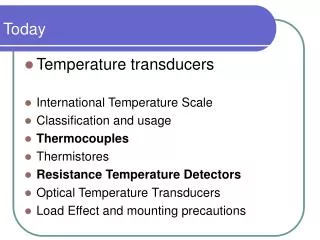
Today • Temperature transducers • International Temperature Scale • Classification and usage • Thermocouples • Thermistores • Resistance Temperature Detectors • Optical Temperature Transducers • Load Effect and mounting precautions
International Temperature Scale While other quantities of the SI are extensive, Temperature is an intensive quantity This makes the implementation of a reference temperature standard difficult… A 25 °C B 25 °C C 25 °C A 10kg B 10kg C 20kg
International Temperature Scale The SI defines as a primary quantity the thermodynamic temperature, defined by Lord Kelvin and based on a Carnot cycle on an ideal gas between two references. While a real gas can behave like an ideal one in a defined range, no gas has the same behaviour in the whole range of temperature required commonly, therefore a set of different practical standards were defined for different temperature ranges Absolute zero0 K = -273.15 °C Water triple point273.16 K = 0.01 °C
International Temperature Scale Actually the valid standard is the ITS-90, which defines the following ranges: • Between 0.65 K and 5.0 K: defined by the vapor-pressure temperature relationship of 3He and 4He. • Between 3.0 K and 24.5561 K (triple point of neon): helium gas thermometer calibrated at 3 fixed points. • Between 13.8033 K (triple point of hydrogen) and 1234.93 K (freezing point of silver): Standard Platinum resistance thermometer (RTD) calibrated at 12 fixed points. • Above 1234.93 K (freezing point of silver): ITS-90 is defined in terms of a defining fixed point and the Planck radiation law.
International Temperature Scale • Between the practical ITS and the absolute thermodynamic scale of the SI there are, actually, minor discrepancies, although the uncertainty arising from them is generally negligible with respect with the transducer overall accuracy. • Given the choice of a common reference interval (0°C – 100°C) an equivalence of 1°C=1 K interval can be used for practical reason • Other equivalences are given byT[K] =t [°C]+273.15=5/9T[°R]=5/9(t [°F]+459.69)kelvin=celsius=rankine=fahrenheit
Temperature Transducers • Thermal Expansion Thermometersbased on a mechanical deformation • Thermocouplesbased on the Seebek-Thomson effect • Resistance based Thermometersbased on the resistance-temperature relation • Optical Systemsbased on the Planck radiation law • Very High Temperature Detectorsbased on gas kinetic theory
Temperature Transducers • Thermal Expansion Thermometers • Liquid based thermometers (usually alcohol based for meteorological measurement) • Gas based thermometers (mostly used in metrological laboratories to calibrate other instruments) • Bimetallic thermometers (usedin industrial sites when time isn'tcritical or for safety devices) T -> x
Temperature Transducers • Thermal Expansion Thermometers • Used only for very slow measurements due to the superimposition of thermal inertia and of mechanical inertia • Digital acquisition from these transducers is difficult and uncommon, other system are today preferred except for metrological laboratories • Probe insertion fraction is relevant, therefore correction factors are required with non standard mountings T1 Tamb
Temperature Transducers Thermocouples • Based on the Seebek and Thomson thermoelectrical effects • Cheap, easy to use, interchangeable and reliable • Follow a standardizedcodification of range and sensitivity • Actually the most commonly found temperature transducer in industrial production T -> V
Temperature Transducers T -> R Resistance based Thermometers • Either based on metallic elements (RTD) or semiconductors (thermistores) resistance dependance on temperature • Accurate and linear measurement only in a very small range of temperature • Requires a conditioning device and proper measuring circuitry to work • Can be implemented directly in a printed circuit • Usually adopted for cheap automatic measurements of for thermal compensations
Temperature Transducers Optical Systems • Based on thermal radiation transfer to either another temperature transducer or a photovoltaic cell • Greatly depends on the colour and emissivity of the body under scrutiny • Contact-less measurement suitable for hostile environment T -> V
Thermocouples (TC) • Very simple temperature transducers created by joining two different metal conductors • Three different thermoelectric effects come into play: • Seebek effect • Peltier effect • Thomson effect
A T1 T2 B E -> Thermocouples (TC) Seebek effect • In a circuit composed of two different metals A and B, if joints are at different temperatures T1 and T2, an electrical voltage E proportional to T2-T1 is present This is the primary measuring principle in thermocouples
A T1 T2 B I -> Thermocouples (TC) Peltier effect • In a circuit composed of two different metals A and B, if a current I is applied a proportional heat transfer occurs coherent with the Seebek effect This is a load effect for the measuring system, but usually negligible if I is low
Thermocouples (TC) Thomson effect • In a conductor with ends at different temperatures a current proportional with the square temperature difference and coherent with the heat transfer along the wire is generated • The effect is fully reversible Q -> I I -> Q T2 T1 I ->
Thermocouples (TC) Thermocouples laws • A set of four empirical laws on thermocouples help make them a modular and reliable system • Thermocouple laws help with applications, mounting and design of temperature transducers based on TCs
International Temperature Scale • Between the practical ITS and the absolute thermodynamic scale of the SI there are, actually, minor discrepancies, although the uncertainty arising from them is generally negligible with respect with the transducer overall accuracy. • Given the choice of a common reference interval (0°C – 100°C) an equivalence of 1°C=1 K interval can be used for practical reason • Other equivalences are given byT[K] =t [°C]+273.15=5/9T[°R]=5/9(t [°F]+459.69)kelvin=celsius=rankine=fahrenheit
Temperature Transducers • Thermal Expansion Thermometersbased on a mechanical deformation • Thermocouplesbased on the Seebek-Thomson effect • Resistance based Thermometersbased on the resistance-temperature relation • Optical Systemsbased on the Planck radiation law • Very High Temperature Detectorsbased on gas kinetic theory
Temperature Transducers • Thermal Expansion Thermometers • Liquid based thermometers (usually alcohol based for meteorological measurement) • Gas based thermometers (mostly used in metrological laboratories to calibrate other instruments) • Bimetallic thermometers (usedin industrial sites when time isn'tcritical or for safety devices) T -> x
Temperature Transducers • Thermal Expansion Thermometers • Used only for very slow measurements due to the superimposition of thermal inertia and of mechanical inertia • Digital acquisition from these transducers is difficult and uncommon, other system are today preferred except for metrological laboratories • Probe insertion fraction is relevant, therefore correction factors are required with non standard mountings T1 Tamb
Temperature Transducers Thermocouples • Based on the Seebek and Thomson thermoelectrical effects • Cheap, easy to use, interchangeable and reliable • Follow a standardizedcodification of range and sensitivity • Actually the most commonly found temperature transducer in industrial production T -> V
Temperature Transducers T -> R Resistance based Thermometers • Either based on metallic elements (RTD) or semiconductors (thermistores) resistance dependance on temperature • Accurate and linear measurement only in a very small range of temperature • Requires a conditioning device and proper measuring circuitry to work • Can be implemented directly in a printed circuit • Usually adopted for cheap automatic measurements of for thermal compensations
Temperature Transducers Optical Systems • Based on thermal radiation transfer to either another temperature transducer or a photovoltaic cell • Greatly depends on the colour and emissivity of the body under scrutiny • Contact-less measurement suitable for hostile environment T -> V
Thermocouples (TC) • Very simple temperature transducers created by joining two different metal conductors • Three different thermoelectric effects come into play: • Seebek effect • Peltier effect • Thomson effect
A T1 T2 B E Thermocouples (TC) Seebek effect • In a circuit composed of two different metals A and B, if joints are at different temperatures T1 and T2, an electrical voltage E proportional to T2-T1 is present This is the primary measuring principle in thermocouples
A T1 T2 B I Thermocouples (TC) Peltier effect • In a circuit composed of two different metals A and B, if a current I is applied a proportional heat transfer occurs coherent with the Seebek effect This is a load effect for the measuring system, but usually negligible if I is low
Thermocouples (TC) Thomson effect • In a conductor with ends at different temperatures and an electrical current along it, heat is generated if the current runs towards the coldest end, and absorbed if otherwise • The effect is fully reversible If T2>T1 then heat is generated If T2<T1 then heat is absorbed q T2 T1 I
Thermocouples (TC) Metals used • A set of metal couples are commonly used in industry to maximize sensitivity and linearity in their range following an international standard that defines also their expected uncertainty
Thermocouples (TC) Thermocouples laws • A set of four empirical laws on thermocouples help make them a modular and reliable system • Thermocouple laws help with applications, mounting and design of temperature transducers based on TCs
A T1 T2 B E Thermocouples (TC) I law: homogenous material • Voltage E generated by a TC is not affected by temperature differences in the conductors, but only by difference in temperature at the junctions with different material This allows for measuring the voltage using an instrument at a temperature different than T1 or T2 T3
Thermocouples (TC) II law: intermediate material • Voltage E generated by a TC is not affected by the insertion of a third conductor given that its ends are the same temperature This allows for measuring soldering the TC to its target and for extension cables if required A T3 T3 T1 T2 B E
A B E Thermocouples (TC) III law: successive material • Voltage E generated by a TC made by materials A and B is equal to the algebraic sum of voltage of a TC made by A and C and of voltage of a TC made by C and B A This allows for a quick characterization of the metal couples for non-standard thermocouples E1 C C E=E1+E2 B E2
A T1 T3 A B E1 T1 T2 B E A T3 T2 B E2 Thermocouples (TC) IV law: successive temperature • Voltage E generated by a TC with temperatures T1 and T2 is equal to the sum of voltage given by the same TC between T1 and T3 and of voltage given between T3 and T2 This make possible to compensate for an ambient temperature and relate all measurement to the reference point E=E1+E2
A T1 T2 B E Thermocouples (TC) Ideal measuring circuit • The reference point is actually recreated at a junction in order for the TC to create a 0°C referenced output COLD JUNCTION Water-Ice bath(melting ice point) HOT JUNCTION object being measured E=f(T2-0°C) High impedance voltmeter (to limit the Peltier, Thomson and Joule effects)
A T1 T2 B E Thermocouples (TC) Practical measuring circuit • The cold junction is at ambient temperature, but a secondary transducer (usually a thermistor) is used to evaluate it, and compensate it using the IV law COLD JUNCTION Isothermal block object being measured E=f(T2-T1)+Ec given Ec=f(T1-0°C) E=f(T2-0°C) High impedance voltmeter + Ec - Thermistor
Thermocouples (TC) Practical Connections • The terminal of a thermocouple could be joint pigtails, soldered end or, most commonly, soldered and protected by a ceramic or metallic shield A trade-off has to be made between robustness of the probe and readiness of the transducer: the massive the sheath or junction, the bigger the thermal inertia involved (therefore the bigger the time constant)
Thermocouples (TC) Thermocouples as elementary transducers • Thermocouples can be connected in series, to create a thermopile, maximizing the sensitivity, or in parallel, to evaluate the average value of temperature in an area
Thermistores • Thermistores are semiconductors, whose resistance dependency on temperature follows the law: LOW ACCURACY SMALL INPUT RANGEHIGH SENSITIVITY Since their behavior is non linear they are used only in small ranges of temperatures, exploiting the fact that they very small and can be easily integrated into printed circuitry
Thermistores • Thermistores are commonly found in printed circuits, in compensating circuits, in temperature-sensible hardware • Apt for rough and measurements except the case of a very narrow input range
Resistance Temperature Detector (RTD – Pt100) • Based on the dependance between resistance and temperature in pure metals:R=pL/A=p(T0)*(1+a(T-T0))L/A • Opposite to thermistorestheir sensitivity is very low, although their accuracy is higher and their input range wider
Resistance Temperature Detector (RTD – Pt100) • Since the a coefficient in Platinum offers a high linearity (0.5%) in the range -200°C - +150°C RTDs are commonly made in platinum and calibrated between 0°C and 100°C • Since in the industrial field the value of R(0°C)=100Ω has become a standard RTDs are often called Pt100 (stands for Platinum RTD with a nominal resistance of 100Ω)
Resistance Temperature Detector (RTD – Pt100) • Since resistance high depends on strain it's important to avoid stressing the probe • A difference in resistance is difficult to read without proper circuitry, therefore these transducers require a set of possible measuring circuitry • There is a parallel with strain gauges due to their very close design and principles
Resistance Temperature Detector (RTD – Pt100) Commonly found circuits: • Quarter bridge (two leads) • Half bridge (three leads) both based on the Wheatstone bridge • Voltamperometer (four leads)the most common one, although requiring some workaround
Wheatstone bridge: principle Introducingresistancevariations and assumingsmallvariationform the samenominalresistancewehave:
R1+R1 R2 V R3 R4+R4 E Wheatstone bridge: principle If the signal is the same we have: • Opposingbranchessignalsaddthemselves up 21
R1+R1 R2 V R4 R3+R3 E Wheatstone bridge: principle If the signal is the same we have: • Adjacentbranchessignals are subtracted 22
Resistance Temperature Detector (RTD – Pt100) The variation in resistance is given by a single branch of the bridge • Wire length tampers the measurement QUARTER BRIDGE Two wires connection
Resistance Temperature Detector (RTD – Pt100) Wire resistance is automatically compensated by moving a branch joint close to the probe HALF BRIDGE Three wires connection
Resistance Temperature Detector (RTD – Pt100) four wires connection Wire resistance is automatically compensated and measurement is simplified. To avoid overheating the RTD a square wave voltage Is is supplied VoltAmperometer