Triaxial Shear Test
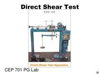
Triaxial Shear Test. CE 317 Geotechnical Engineering Dr. Tae-Hyuk Kwon. Chapter 11. Laboratory tests on specimens taken from representative undisturbed samples. Field tests. Most common laboratory tests to determine the shear strength parameters are, Direct shear test

Triaxial Shear Test
E N D
Presentation Transcript
Triaxial Shear Test CE 317 Geotechnical Engineering Dr. Tae-Hyuk Kwon Chapter 11
Laboratory tests on specimens taken from representative undisturbed samples Field tests • Most common laboratory tests to determine the shear strength parameters are, • Direct shear test • Triaxial shear test • Vane shear test • Torvane • Pocket penetrometer • Fall cone • Pressuremeter • Static cone penetrometer • Standard penetration test Determination of shear strength parameters of soils (c, forc’, f’) Other laboratory tests include, Direct simple shear test, torsional ring shear test, plane strain triaxial test, laboratory vane shear test, laboratory fall cone test
A representative soil sample z z svc + Ds svc shc shc shc shc svc svc + Ds After and during construction Before construction Laboratory tests Field conditions
svc + Ds shc shc Traxial test 0 svc svc + Ds svc shc shc 0 0 t Direct shear test svc 0 t svc Representative soil sample taken from the site Step 1 Set the specimen in the apparatus and apply the initial stress condition Laboratory tests Simulating field conditions in the laboratory Step 2 Apply the corresponding field stress conditions
Piston (to apply deviatoric stress) Failure plane O-ring impervious membrane Soil sample Soil sample at failure Porous stone Perspex cell Water Cell pressure Pore pressure or volume change Back pressure pedestal Triaxial Shear Test
Sampling tubes Sample extruder Triaxial Shear Test Specimen preparation (undisturbed sample)
Setting up the sample in the triaxial cell Edges of the sample are carefully trimmed Triaxial Shear Test Specimen preparation (undisturbed sample)
Sample is covered with a rubber membrane and sealed Cell is completely filled with water Triaxial Shear Test Specimen preparation (undisturbed sample)
Proving ring to measure the deviator load Dial gauge to measure vertical displacement Triaxial Shear Test Specimen preparation (undisturbed sample)
deviatoric stress ( = q) c Step 2 Step 1 c c c c c+ q c Under all-around cell pressure c Shearing (loading) yes no yes no Consolidated sample Undrained loading Drained loading Unconsolidated sample Types of Triaxial Tests Is the drainage valve open? Is the drainage valve open?
Step 2 Step 1 Under all-around cell pressure c Shearing (loading) Is the drainage valve open? Is the drainage valve open? CD test UU test yes no yes no Consolidated sample Undrained loading Drained loading Unconsolidated sample CU test Types of Triaxial Tests
= + Total, s Effective, s’ Neutral, u sVC s’VC =sVC shC s’hC =shC 0 Drainage Drainage Drainage sVC + Ds sVC + Dsf s’V =sVC +Ds = s’1 shC shC s’h =shC = s’3 0 0 s’Vf =sVC +Dsf= s’1f s’hf =shC = s’3f Consolidated- drained test (CD Test) Step 1: At the end of consolidation Step 2: During axial stress increase Step 3: At failure
s1 = sVC + Ds s3 = shC Consolidated- drained test (CD Test) Deviator stress (q or Dsd) = s1 – s3
Time Expansion Volume change of the sample Compression Consolidated- drained test (CD Test) Volume change of sample during consolidation
Deviator stress, Dsd Dense sand or OC clay (Dsd)f Loose sand or NC Clay (Dsd)f Axial strain Expansion Dense sand or OC clay Volume change of the sample Axial strain Compression Loose sand or NC clay Consolidated- drained test (CD Test) Stress-strain relationship during shearing
Deviator stress, Dsd s1 = s3 + (Dsd)f (Dsd)fc Confining stress = s3c s3 Confining stress = s3b Confining stress = s3a (Dsd)fb Axial strain (Dsd)fa Shear stress, t f Mohr – Coulomb failure envelope s or s’ s3c s3a s3b s1a s1b s1c (Dsd)fa (Dsd)fb CD tests How to determine strength parameters c and f
Strength parameters c and f obtained from CD tests CD tests Therefore, c = c’ and f = f’ Since u = 0 in CD tests, s = s’ cd and fd are used to denote them
fd Mohr – Coulomb failure envelope Shear stress, t s or s’ s3a s1a (Dsd)fa CD tests Failure envelopes For sand and NC Clay, cd = 0 Therefore, one CD test would be sufficient to determine fd of sand or NC clay
NC OC t f s or s’ c s3 s1 sc (Dsd)f CD tests Failure envelopes For OC Clay, cd ≠ 0
Soft clay t Some practical applications of CD analysis for clays 1. Embankment constructed very slowly, in layers over a soft clay deposit t = in situ drained shear strength
t Core t = drained shear strength of clay core Some practical applications of CD analysis for clays 2. Earth dam with steady state seepage
t Some practical applications of CD analysis for clays 3. Excavation or natural slope in clay t = In situ drained shear strength Note: CD test simulates the long term condition in the field. Thus, cd and fd should be used to evaluate the long term behavior of soils
= + Total, s Effective, s’ Neutral, u sVC s’VC =sVC shC s’hC =shC 0 Drainage s’V =sVC +Ds ± Du = s’1 sVC + Ds sVC + Dsf No drainage shC shC s’h =shC ± Du= s’3 ±Du s’Vf =sVC +Dsf± Duf = s’1f No drainage s’hf =shC ± Duf = s’3f ±Duf Consolidated- Undrained test (CU Test) Step 1: At the end of consolidation Step 2: During axial stress increase Step 3: At failure
Time Expansion Volume change of the sample Compression Consolidated- Undrained test (CU Test) Volume change of sample during consolidation
Deviator stress, Dsd Dense sand or OC clay (Dsd)f Loose sand or NC Clay (Dsd)f Axial strain + Loose sand /NC Clay Du Axial strain - Dense sand or OC clay Consolidated- Undrained test (CU Test) Stress-strain relationship during shearing
Deviator stress, Dsd (Dsd)fb s1 = s3 + (Dsd)f Confining stress = s3b Confining stress = s3a s3 (Dsd)fa Axial strain Total stresses at failure Shear stress, t fcu Mohr – Coulomb failure envelope in terms of total stresses s or s’ ccu s3b s3a s1a s1b (Dsd)fa CU tests How to determine strength parameters c and f
s’1 = s3 + (Dsd)f -uf s’3= s3 -uf Mohr – Coulomb failure envelope in terms of effective stresses Shear stress, t f’ ufb s or s’ ufa C’ s’3b s’1b s3b s3a s’3a s1a s1b s’1a (Dsd)fa (Dsd)fa CU tests How to determine strength parameters c and f uf Effective stresses at failure Mohr – Coulomb failure envelope in terms of total stresses fcu ccu
Strength parameters c and f obtained from CD tests CU tests Shear strength parameters in terms of effective stresses are c’ and f’ Shear strength parameters in terms of total stresses are ccu and fcu c’ = cd and f’ = fd
Mohr – Coulomb failure envelope in terms of effective stresses f’ fcu Mohr – Coulomb failure envelope in terms of total stresses Shear stress, t s3a s1a s or s’ s3a s1a (Dsd)fa CU tests Failure envelopes For sand and NC Clay, ccu and c’ = 0 Therefore, one CU test would be sufficient to determine fcu and f’(= fd) of sand or NC clay
Soft clay t Some practical applications of CU analysis for clays 1. Embankment constructed rapidly over a soft clay deposit t = in situ undrained shear strength
t Some practical applications of CU analysis for clays 2. Rapid drawdown behind an earth dam Core t = Undrained shear strength of clay core
t t = In situ undrained shear strength Some practical applications of CU analysis for clays 3. Rapid construction of an embankment on a natural slope Note: Total stress parameters from CU test (ccu and fcu) can be used for stability problems where, Soil have become fully consolidated and are at equilibrium with the existing stress state; Then for some reason additional stresses are applied quickly with no drainage occurring
0 0 s’3 =s3 - Duc sC = s3 s’3 =s3 - Duc Duc sC = s3 No drainage Increase of cell pressure Increase of pwp due to increase of cell pressure Skempton’s pore water pressure parameter, B Unconsolidated- Undrained test (UU Test) Step 1: Immediately after sampling Step 2: After application of hydrostatic cell pressure = + Duc =B Ds3 Note: If soil is fully saturated, then B = 1 (hence, Duc = Ds3)
= + Total, s Effective, s’ Neutral, u s’V0 =ur 0 s’h0 =ur -ur 0 s’VC =sC +ur -sC=ur sC -ur + Duc = -ur + sc (S = 100%) s’h =ur sC s’V =sC +Ds + ur - scDu No drainage sC + Ds sC s’h =sC +ur - scDu -ur + sc ± Du s’Vf =sC +Dsf+ ur - scDuf = s’1f sC + Dsf No drainage No drainage s’hf =sC +ur - scDuf = s’3f sC -ur + sc ± Duf Unconsolidated- Undrained test (UU Test) Step 1: Immediately after sampling Step 2: After application of hydrostatic cell pressure Step 3: During application of axial load Step 3: At failure
= + Total, s Effective, s’ Neutral, u Step 3: At failure t s’Vf =sC +Dsf+ ur - scDuf = s’1f sC + Dsf s’ No drainage s’1 s’3 s’hf =sC +ur - scDuf = s’3f Dsf sC -ur + sc ± Duf Unconsolidated- Undrained test (UU Test) Mohr circle in terms of effective stresses do not depend on the cell pressure. Therefore, we get only one Mohr circle in terms of effective stress for different cell pressures
= + Total, s Effective, s’ Neutral, u Step 3: At failure Failure envelope, fu = 0 t cu s’Vf =sC +Dsf+ ur - scDuf = s’1f ua ub sC + Dsf No drainage s1b s3b s’3 s1a s3a s’1 s or s’ s’hf =sC +ur - scDuf = s’3f Dsf sC -ur + sc ± Duf Unconsolidated- Undrained test (UU Test) Mohr circles in terms of total stresses
t s3b s1c s3c s1b s3a s1a s or s’ Unconsolidated- Undrained test (UU Test) Effect of degree of saturation on failure envelope S < 100% S > 100%
Soft clay t Some practical applications of UU analysis for clays 1. Embankment constructed rapidly over a soft clay deposit t = in situ undrained shear strength
t Core t = Undrained shear strength of clay core Some practical applications of UU analysis for clays 2. Large earth dam constructed rapidly with no change in water content of soft clay
t = In situ undrained shear strength Some practical applications of UU analysis for clays 3. Footing placed rapidly on clay deposit Note: UU test simulates the short term condition in the field. Thus, cu can be used to analyze the short term behavior of soils
Unconfined Compression Test (UC Test) s1 = sVC + Ds s3 = 0 Confining pressure is zero in the UC test
s1 = sVC + Dsf Shear stress, t s3 = 0 qu Normal stress, s Unconfined Compression Test (UC Test) τf= σ1/2 = qu/2 = cu