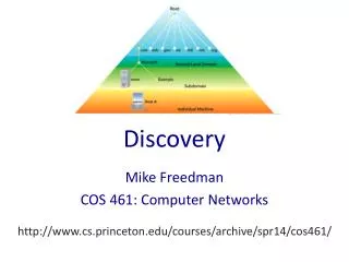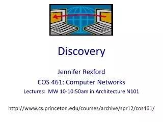
Discovery
Discovery. Neighbor Discovery. Motivations and previous approaches Data Plane Discovery Functionality OIF UNI Discovery G.7714.1 Discovery Control Plane “Discovery” Functionality GMPLS’ LMP. Discovery Motivation. Who is on the other side of the link?

Discovery
E N D
Presentation Transcript
Discovery © Grotto Networking 2004
Neighbor Discovery • Motivations and previous approaches • Data Plane Discovery • Functionality • OIF UNI Discovery • G.7714.1 Discovery • Control Plane “Discovery” • Functionality • GMPLS’ LMP © Grotto Networking 2004
Discovery Motivation • Who is on the other side of the link? • Analogy: The human “hello protocol” It’s Mr. Blue. Let’s tell him who I am and check his name. Let me find out who that is… Hello, I’m Mr. Blue It’s Ms. Orange and she got my name right. Hi, Mr. Blue, I’m Ms. Orange Nice to meet you Ms. Orange. Let me double check that I got her name right Confirmed that Mr. Blue has got my name right. © Grotto Networking 2004
But is it worth the effort? • Early days of optical networking very few fibers and no standard protocols for this function No. • Current technology lots of fibers Yes! With commercially available modern DWDM systems, one long-haul fiber pair can contain more than 100 channels, which get broken out into individual fiber pairs at end systems and regenerators. © Grotto Networking 2004
Neighbor Discovery (Why bother?) • A single box can have lots of neighbors! • Modern SONET/SDH and WDM equipment can support many ports! 256 ports of OC-48 © Grotto Networking 2004
Inconsistent Wiring Issues • Consider a bidirectional 1+1 fiber pair • Works fine under normal conditions • Works fine if we lose a fiber, 1+1 protection. • Maintenance operation: Replace bad fiber Port 1 Port 12 Conduit Port 13 Port 2 Box A Box B © Grotto Networking 2004
Inconsistent Wiring Problems • Undetected miss-wiring • Big problem we just pulled the wrong fiber!!! Now Box A can’t hear from Box B. Port 1 Port 12 Port 13 Port 2 Box A Box B © Grotto Networking 2004
Why do Neighbor Discovery? • Allows automatic inventory of physical links between nodes • Can determine inconsistent physical wiring • Allows automatic identification of node-pair neighbors • Supports accurate neighbor link information for use in routing and signaling © Grotto Networking 2004
Existing Neighbor Discovery Protocols • A subclass of IP routing protocols contain a “hello” sub-protocol. • These are known as Interior Gateway Protocols (IGPs). • The most widely used IGPs are OSPFv2 and IS-IS • OSPFv2 is documented in RFC2328 and is available from www.ietf.org © Grotto Networking 2004
OSPF’s Hello Protocol • Neighbor Discovery (bi-directional communications) • Designated Router Election for LANs • Dead Router Detection OSPF Hello packet is carried in an IP datagram © Grotto Networking 2004
OSPF’s Hello Protocol • Neighbor State Machine © Grotto Networking 2004
A Solution Exists, can we go home? No, transport networks (optical in particular) have two complicating factors: • Layers in transport networks • Both in WDM and TDM systems makes the question a bit more complicated. • Separation of Control and Data Planes • Further complicates things and gives us more to discover… © Grotto Networking 2004
Layers in WDM Networks © Grotto Networking 2004
Layers in TDM Networks © Grotto Networking 2004
SONET/SDH Layers… 1.5Mbps – 6Mbps J2 VT trace Multiplexing here J1 Path trace 50Mbps – 40Gbps Multiplexing here No Line trace J0 section trace © Grotto Networking 2004
Neighbor Discovery at which layer? PLR-PLR neighbor discovery STE-STE neighbor discovery STE-STE neighbor discovery PLR PLR STE PTE PTE LTE LTE STE LTE-LTE neighbor discovery PLR-PLR neighbor discovery Definitions PLR - Physical Layer Regenerator STE - Section Terminating Equipment LTE - Line Terminating Equipment PTE - Path Terminating Equipment © Grotto Networking 2004
Generalized Automatic Discovery ITU G.7714 Concepts • Layer Adjacency Discovery • Who are my neighbor peers? • Physical Media Adjacency Discovery • What is the next box I’m physically connected to? • Control Entity Logical Adjacency Establishment • If we are going to participate in a control protocol who should I talk to? • Service Capability Exchange • What kinds of things can your peer box or subnetwork do? How are you configured? Data Plane Data Plane Control Plane Control Plane © Grotto Networking 2004
Layer Adjacency Discovery • Who is my “peer” at a particular layer in the transport system. • Similar to the connectivity supervision management task • Answers the question: Am I connected to the right end point? • Usually continuously monitored • General mechanism for this is a “trail trace” © Grotto Networking 2004
Trail Trace in SONET/SDH Section (regenerator section) trace J0 Section DCC Line (multiplex section) DCC © Grotto Networking 2004
Trail Trace in SONET/SDH… Path (HO-VC) trace J1 Contains TCM layer trace and other items © Grotto Networking 2004
Trail Trace Summary • Primary usage • Detecting miss-connected signals at various layers in the transport hierarchy. Exists for Path (HO-VC), VT (LO-VC), TCM and Section layers and for most OTN layers. Conspicuously missing from Line (Multiplex Section) layer. • Operation • Trace text string (16 or 64 characters) is set via a management system. • Expected trace (what you should be getting) is also set via a management system. • Supervision is accomplished by enabling alarms if the expected trace doesn’t match the received trace. © Grotto Networking 2004
J0-Based Neighbor Discovery via EMS Compare EMS Report A, Z Values Report Z, A Values Out-of-band Control A: TID, AID Z: TID, AID © Grotto Networking 2004
Issues • The previous method dumps most of the work back to the EMS • Doesn’t necessarily blend with the rest of the control plane • How are the values of the traces filled in? • May not work between domains (need some type of agreement, i.e., a standard!) • Doesn’t work for the Line (multiplex section layer) since no trace • The line layer is very important since most ADM and high capacity cross connects work at this layer. © Grotto Networking 2004
ITU-T G.7714.1 Discovery Protocol Protocol for automatic discovery in SDH and OTN networks • Use of Trail Trace • Specific encoding of trace string with (node, port) information. • Node identification relevant to the control plane • Use of a DCC/GCC • For layers without trail trace a set of messages exchanged over the data communications channel (DCC) or General Communications Channel (GCC), that are part of the overhead for that layer. © Grotto Networking 2004
G.7714.1 Discovery Mechanisms SDH Mechanisms from G.7714.1 • RS layer: • Within the RS layer, the J0 section trace and Section DCC may be used to support discovery of the RS TCP-to-TCP adjacency. • MS layer: • Within the MS layer, the Multiplex Section DCC may be used to support discovery of the MS TCP-to-TCP adjacency. • HOVC layer: • Within the HOVC layer, the higher order Path layer J1 trace may be used to support discovery of the HOVC TCP-to-TCP adjacency. • LOVC layer: • Within the LOVC layer, the lower order Path layer J2 trace may be used to support discovery of the LOVC TCP-to-TCP adjacency. © Grotto Networking 2004
G.7714.1 Discovery Mechanisms OTN Mechanisms from G.7714.1 • OTUk layer: • Within the OTUk layer the SM section monitoring bytes and the GCC0 may be used to support discovery of the OTUk adjacency. Specifically, the SAPI subfield within the SM is used to carry the discovery message. • ODUk layer: • Within the ODUk layer the PM path monitoring bytes and the GCC-1 and GCC-2 bytes may be used to support discovery of the ODUk adjacency. Specifically, the SAPI subfield within the PM is used to carry the discovery message. © Grotto Networking 2004
OTUk Frame Format From G.709 Use the SAPI (source access point identifier) portion of the TTI (trail trace identifier) for G.7714.1 discovery. © Grotto Networking 2004
ODUk Frame Format Use the SAPI (source access point identifier) portion of the TTI (trail trace identifier) for G.7714.1 discovery. © Grotto Networking 2004
G.7714.1 Information formats Generally we need some type of node and port identifier. However this information may be shared in three different ways: • TCP Name Format • In this case a single identifier is used and can be resolved into the node and port ID via a name server. Keeps carrier network details completely hidden • DA DCN Address Format • In this case the node ID is the actual address of the control entity, known as the discovery agent, responsible for the discovery process. The port ID is also included. © Grotto Networking 2004
G.7714.1 Information formats (cont.) Generally we need some type of node and port identifier. However this information may be shared in three different ways: • DA DCN Name Format • In this case which is similar to the DA DCN Address format, the node name is given and can be resolved to the DA address via a name server. This format is useful when longer DCN addresses such as IPv6 format addresses are used. The port ID is also included. © Grotto Networking 2004
G.7714.1 Discovery Message • Key design objective (accomplished) • One generic message format to be used for all different trail trace and DCC/GCC discovery processes. • Compatibility with existing implementations • Implications • Message must fit into the severely space limited J0 section trace message. • Total of 16 bytes. One byte used for CRC, One for distinguishing character, of remaining 14 bytes we can only use 7 out of 8 bits (compatibility with ITU-T T.50 character set). Additional compatibility requires the use of printable characters! © Grotto Networking 2004
G.7714.1 Discovery Message Encoding • 14 character slots (7 bit bytes restricted to printable characters) available • IETF RFC 2045 base64 encoding • Maps 6 binary bits into a single printable character • 14 Characters 6*14 = 84 bits available © Grotto Networking 2004
G.7714.1 Discovery Message Formats TCP-ID Name Message format DA DCM Address Message format DA DCM Name Message format © Grotto Networking 2004
G.7714.1 procedures • For Trace based mechanism • Use the desired message format as the trace string. • For DCC/GCC mechanism • Choose either LAPD or PPP: • LAPD use unnumbered information transfer (UIT) mode to send message. • PPP use PPP LCP extension (RFC1570) packet type 12 (identification) with the message as the message! • Discovery Response Message • May be sent specifying the node and port that just received the sent message. How this is done is not currently specified in G.7714.1 © Grotto Networking 2004
OIF UNI 1.0/1.1 Discovery • DCC based • Uses either line (multiplex section) or section (regenerator section) data communications channel (DCC) • Uses IETF LMP message Format • This usage is not specified in the IETF’s Link Management Protocol (LMP), but is specified in the UNI1.0/1.1 documents available without charge at www.oiforum.com © Grotto Networking 2004
OIF UNI modified LMP Config Procedure Config Messages sent over each control channel Config Ack/Nack Node ID Message ID Config Objects CCID Config Message Node ID: Sending Node ID; CCID: Port number Msg ID: Unique ID assigned by sending node Hello Dead Interval Hello Interval Hello Config Object Hello Int. : Frequency of Hello messages; Hello Dead Int.: Waiting time before declaring neighbor dead © Grotto Networking 2004
Verifying Port Connectivity Config (Node ID = 192.28.134.2 , CCID = 1) 4 R 1 T T R ConfigAck (Node ID = 198.28.134.5, CCID = 4, Recd. Node ID = 192.28.134.2, Rcv. CC ID = 1) Config (Node ID = 192.28.134.2 , CCID = 3) R 6 3 T T R ConfigAck (Node ID = 198.28.134.5, CC ID = 6, Recd. Node ID = 192.28.134.2, Rcv. CC ID = 3) OXC Client Node ID = 192.28.134.5 Node ID = 192.28.134.2 © Grotto Networking 2004
Detecting Incorrect Wiring N1 (192.14.15.2) N2 (192.15.2.3) T T 10 1 Config (N1, msg=1, ccid=1) R R Config (N1, msg=2, ccid=2) T T Exchanges at N1,P1 and N1,P2 11 2 Ack (N2,ccid = 10, msg=2, N1, rccid=2) R R Ack (N2,ccid = 11, msg=1, N1, rccid=1) T T 12 3 R R © Grotto Networking 2004
Physical Media Adjacency Discovery • Who’s my physical neighbor? • Currently no standards but there has been some good work in this area. • Simple Optical Neighbor Discovery (SOND) • Idea: create low speed communications channel at link turn up for sending/receiving discovery information • Uses the Laser Shutdown (LS) signal to transmit information and the Loss of Signal (LOS) indication to receive information. • Reference: Stefan N. Larsson, Sten Hubendick, and Robert Nedelchef, Wavium AB, “Simple optical neighbor discovery (SOND): architecture, applications, and experimental verification”,October 2003, Journal of Optical Networking. © Grotto Networking 2004
Control Entity Adjacency Establishment • Concept: separation of control and data plane • Control traffic does not run over the “data plane” • Link overhead may furnish part of the control plane network. IP Network IPb IPd LTE or PXC LTE or PXC Data Plane IPa IPc IP Network Control Plane © Grotto Networking 2004
Control Entity Adjacency Establishment • How do we find out who our neighbor control entity is? (at a given layer) • Provision this information • Obtain this information via layer adjacency discovery, I.e., the “DCN address” is the address of the control entity. • How do we establish and maintain the communications “channel” between these entities? • The IETF’s Link Management Protocol (LMP) has procedures for Control Channel Management • In does this via a Config procedure which verifies bidirectional connectivity and a heartbeat procedure (named Hello) to monitor connectivity. © Grotto Networking 2004
LMP Messages • LMP messages run over UDP (User Datagram Protocol) • Control Channel Management Messages • Link Property Correlation Messages • Link Verification Messages (optional not really needed for SDH/OTN) • Fault Management Messages (optional not really needed for SDH/OTN) Two flags: Control channel down, and LMP restart © Grotto Networking 2004
LMP Objects • LMP Messages consist of LMP Objects of the following form • N indicates whether the object is negotiable • C-Type is the generic class type of the object • Class is the particular type of object, e.g., an IPv4 address versus an IPv6 address © Grotto Networking 2004
LMP Link Management Messages • Config Message (starts the conversation rolling) • ::= <Common Header> <LOCAL_CCID> <MESSAGE_ID> <LOCAL_NODE_ID> <CONFIG> • ConfigAck Message (used to establish two way connectivity) • ::= <Common Header> <LOCAL_CCID> <LOCAL_NODE_ID><REMOTE_CCID> <MESSAGE_ID_ACK> <REMOTE_NODE_ID> • ConfigNack Message • ::= <Common Header> <LOCAL_CCID><LOCAL_NODE_ID> <REMOTE_CCID><MESSAGE_ID_ACK><REMOTE_NODE_ID> <CONFIG> • Hello Message (used as a heartbeat) • ::= <Common Header> <LOCAL_CCID> <HELLO> © Grotto Networking 2004
LMP Link Summary Messages • LinkSummary Message • ::= <Common Header> <MESSAGE_ID> <TE_LINK> <DATA_LINK> [<DATA_LINK>...] • LinkSummaryAck Message • ::= <Common Header> <MESSAGE_ID_ACK> • LinkSummaryNack Message • ::= <Common Header> <MESSAGE_ID_ACK><ERROR_CODE> [<DATA_LINK>...] © Grotto Networking 2004
LMP Functions Conceptual “control channel” created and maintained via LMP config and hello messages. IP Network IPa IPb Control for A Control for B Conceptual “TE link”, a bundle of real links agreed upon via LMP summary messages. © Grotto Networking 2004
Discovery Summary • Which layer should I discover? • Generally rule: all layers that you process. • Most important for layers that you switch at. • What functionality do I want? • Automatic inventory of links • Uni-directional as in G.7714.1 • Bi-directional wiring verification • Extra procedure in G.7714.1 may use some LMP messages • Bootstrap G.ASON/GMPLS control plane • Bring up control channel • Bundle parallel lines into “TE links” for representation in routing protocols. © Grotto Networking 2004
Status • Interoperability • No significant demonstration of neighbor discovery interoperability yet… • But standardization of G.7714.1 should help. • Deployment • A variety of proprietary implementations typically tied to link state protocols running over line or section DCC are being used in production transport networks • Integration with existing OSS © Grotto Networking 2004