Chapter 2-Webster Basic Sensors and Principles
Chapter 2-Webster Basic Sensors and Principles. Transducer, Sensor, and Actuator. Transducer : a device that converts energy from one form to another Sensor : converts a physical parameter to an electrical output (a type of transducer, e.g. a microphone)

Chapter 2-Webster Basic Sensors and Principles
E N D
Presentation Transcript
Chapter 2-Webster Basic Sensors and Principles
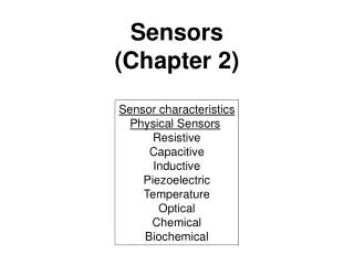
Transducer, Sensor, and Actuator Transducer: a device that converts energy from one form to another Sensor: converts a physical parameter to an electrical output (a type of transducer, e.g. a microphone) Actuator: converts an electrical signal to a physical output (opposite of a sensor, e.g. a speaker) • Type of Sensors • Displacement Sensors: • resistance, inductance, capacitance, piezoelectric • Temperature Sensors: • Thermistors, thermocouples • Electromagnetic radiation Sensors: • Thermal and photon detectors
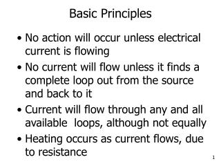
Displacement Measurements Used to measure directly and indirectly the size, shape, and position of the organs. Displacement measurements can be made using sensors designed to exhibit a resistive, inductive, capacitive or piezoelectric change as a function of changes in position.
Resistive sensors - potentiometers Measure linear and angular position Resolution a function of the wire construction Measure velocity and acceleration 2 to 500mm 10o and more
Resistive sensors – strain gages Devices designed to exhibit a change in resistance as a result of experiencing strain to measure displacement in the order of nanometer. For a simple wire: A change in R will result from a change in (resistively), or a change in L or A (dimension). The gage factor, G, is used to compare various strain-gage materials Is Poisson’s ratio Semiconductor has larger G but more sensitive to temperature
Wheatstone Bridge vo is zero when the bridge is balanced- that is when Show Proof in class If all resistor has initial value R0 then if R1 and R3 increase by R, and R2 and R4 decreases by R, then Show Proof in class
Unbonded strain gage: With increasing pressure, the strain on gage pair B and C is increased, while that on gage pair A and D is decreased. Initially before any pressure R1 = R4 and R3 = R2 Wheatstone Bridge A B D C Error in Fig. 2.2 legend: R1 = A, R2 = B, R3 = D, R4 = C
Bonded strain gage: - Metallic wire, etched foil, vacuum-deposited film or semiconductor is cemented to the strained surface - Rugged, cheap, low mass, available in many configurations and sizes - To offset temperature use dummy gage wire that is exposed to temperature but not to strain
Bonded strain gage terminology: Carrier (substrate + cover)
Semiconductor Integrated Strain Gages Pressure strain gages sensor with high sensitivity Integrated cantilever-beam force sensor
4 cm Clear plastic Saline Flush valve To patient IV tubing Gel Silicon chip Electrical cable Figure 14.15 Isolation in a disposable blood-pressure sensor. Disposable blood pressure sensors are made of clear plastic so air bubbles are easily seen. Saline flows from an intravenous (IV) bag through the clear IV tubing and the sensor to the patient. This flushes blood out of the tip of the indwelling catheter to prevent clotting. A lever can open or close the flush valve. The silicon chip has a silicon diaphragm with a four-resistor Wheatstone bridge diffused into it. Its electrical connections are protected from the saline by a compliant silicone elastomer gel, which also provides electrical isolation. This prevents electric shock from the sensor to the patient and prevents destructive currents during defibrillation from the patient to the silicon chip.
Elastic-Resistance Strain Gages Extensively used in Cardiovascular and respiratory dimensional and volume determinations. As the tube stretches, the diameter decreases and the length increases, causing the resistance to increase b) venous-occlusion plethysmography c) arterial-pulse plethysmography Filled with a conductive fluid (mercury, conductive paste, electrolyte solution. Resistance = 0.02 - 2 /cm, linear within 1% for 10% of maximal extension
Inductive Sensors Ampere’s Law: flow of electric current will create a magnetic field Faraday’s Law: a magnetic field passing through an electric circuit will create a voltage i + + + v2 v1 v - - - N2 N1
Inductive Sensors Ampere’s Law: flow of electric current will create a magnetic field Faraday’s Law: a magnetic field passing through an electric circuit will create a voltage Self-inductance Mutual inductance Differential transformer n = number of turns of coil G = geometric form factor m = effective magnetic permeability of the medium
+ - + - LVDT : Linear variable differential transformer - full-scale displacement of 0.1 to 250 mm - 0.5-2 mV for a displacement of 0.01mm - sensitivity is much higher than that for strain gages Disadvantage requires more complex signal processing http://www.macrosensors.com/lvdt_macro_sensors/lvdt_tutorial/lvdt_primer.pdf + _ (a) As x moves through the null position, the phase changes 180, while the magnitude of vo is proportional to the magnitude of x. (b) An ordinary rectifier-demodulator cannot distinguish between (a) and (b), so a phase-sensitive demodulator is required.
Capacitive Sensors Capacitive sensors For a parallel plate capacitor: 0 = dielectric constant of free space r = relative dielectric constant of the insulator A = area of each plate x = distance between plates Change output by changing r (substance flowing between plates), A (slide plates relative to each other), or x.
Sensitivity of capacitor sensor, K Sensitivity increases with increasing plate size and decreasing distance When the capacitor is stationary xo the voltage v1=E. A change in position x = x1 -xo produces a voltage vo = v1 – E. i + + Characteristics of capacitive sensors: High resolution (<0.1 nm) Dynamic ranges up to 300 µm (reduced accuracy at higher displacements) High long term stability (<0.1 nm / 3 hours) Bandwidth: 20 to 3 kHz
Piezoelectric Sensors Measure physiological displacement and record heart sounds. • Certain materials generate a voltage when subjected to a mechanical strain, or undergo a change in physical dimensions under an applied voltage. • Uses of Piezoelectric • External (body surface) and internal (intracardiac) phonocardiography • Detection of Korotkoff sounds in blood-pressure measurements • Measurements of physiological accelerations • Provide an estimate of energy expenditure by measuring acceleration due to human movement.
Vo (typically pC/N, a material property) k for Quartz = 2.3 pC/N k for barium titanate = 140 pC/N To find Vo, assume system acts like a capacitor (with infinite leak resistance): Capacitor: For piezoelectric sensor of 1-cm2 area and 1-mm thickness with an applied force due to a 10-g weight, the output voltage v is 0.23 mV for quartz crystal 14 mV for barium titanate crystal.
Models of Piezoelectric Sensors Piezoelectric polymeric films, such as polyvinylidence fluoride (PVDF). Used for uneven surface and for microphone and loudspeakers.
Transfer Function of Piezoelectric Sensors View piezoelectric crystal as a charge generator: Rs: sensor leakage resistance Cs: sensor capacitance Cc: cable capacitance Ca: amplifier input capacitance Ra: amplifier input resistance Ra
Transfer Function of Piezoelectric Sensors Convert charge generator to current generator: Ra Current Ra Ks = K/C, sensitivity, V/m = RC, time constant
Voltage-output response of a piezoelectric sensor to a step displacement x. Decay due to the finite internal resistance of the PZT The decay and undershoot can be minimized by increasing the time constant =RC.
Example 2.1 C = 500 pF Rleak= 10 G Ra = 5 M What is fc,low ? Current
Temperature Measurement • The human body temperature is a good indicator of the health and physiological performance of different parts of the human body. • Temperature indicates: • Shock by measuring the big-toe temperature • Infection by measuring skin temperature • Arthritis by measuring temperature at the joint • Body temperature during surgery • Infant body temperature inside incubators • Temperature sensors type • Thermocouples • Thermistors • Radiation and fiber-optic detectors • p-n junction semiconductor (2 mV/oC)
Thermocouple A T2 T1 T1 B B E = f(T1 –T2) Electromotive force (emf) exists across a junction of two dissimilar metals. Two independent effects cause this phenomena: 1- Contact of two unlike metals and the junction temperature (Peltier) 2- Temperature gradients along each single conductor (Lord Kelvin) E = f (T12 - T22) Advantages of Thermocouple fast response (=1ms), small size (12 μm diameter), ease of fabrication and long-term stability Disadvantages Small output voltage, low sensitivity, need for a reference temperature
Thermocouple A T2 T1 T1 B B E = f(T1 –T2) Empirical calibration data are usually curve-fitted with a power series expansion that yield the Seebeck voltage. T: Temperature in Celsius Reference junction is at 0 oC
Thermocouple Laws • 1- Homogeneous Circuit law: A circuit composed of a single homogeneous metal, one cannot maintain an electric current by the application of heat alone. See Fig. 2.12b • 2- Intermediate Metal Law: The net emf in a circuit consisting of an interconnection of a number of unlike metals, maintained at the same temperature, is zero. See Fig. 2.12c • Second law makes it possible for lead wire connections • 3- Successive or Intermediate Temperatures Law: See Fig. 2.12d • The third law makes it possible for calibration curves derived for a given reference-junction temperature to be used to determine the calibration curves for another reference temperature. T3 T1 T2
A T2 T1 B E = f(T1 –T2) Thermoelectric Sensitivity For small changes in temperature: Differentiate above equation to find , the Seebeck coefficient, or thermoelectric sensitivity. Generally in the range of 6.5 - 80 V/oC at 20 oC.
Thermistors • Thermistors are semiconductors made of ceramic materials whose resistance decreases as temperature increases. • Advantages • Small in size (0.5 mm in diameter) • Large sensitivity to temperature changes (-3 to -5% /oC) • Blood velocity • Temperature differences in the same organ • Excellent long-term stability characteristics (R=0.2% /year) • Disadvantages • -Nonlinear • -Self heating • -Limited range
R3 R1 V vb va R2 Rt Circuit Connections of Thermistors Bridge Connection to measure voltage Amplifier Connection to measure currents
Thermistors Resistance Relationship between Resistance and Temperature at zero-power resistance of thermistor. 1000 100 = material constant for thermistor, K (2500 to 5000 K) To = standard reference temperature, K To = 293.15 K = 20C = 68F 10 1 Resistance ratio, R/R25º C 0.1 Temperature coefficient 0.01 0.001 is a nonlinear function of temperature - 50 0 50 100 150 200 Temperature, ° C (a) Figure 2.13 (a) Typical thermistor zero-power resistance ratio-temperature characteristics for various materials.
B 10 kW 100 1 M W 1 kW 100 k W A 100 W C Water 10 10 kW Air Voltage, V 1 W 1.0 0.1 mW 1 mW 10 mW 100 mW 0.1 0.10 1.0 10.0 100.0 Current, mA (b) Voltage-Versus-Current Characteristics The temperature of the thermistor is that of its surroundings. However, above specific current, current flow generates heat that make the temperature of the thermistor above the ambient temperature. Figure 2.13 (b) Thermistor voltage-versus-current characteristic for a thermistor in air and water. The diagonal lines with a positive slope give linear resistance values and show the degree of thermistor linearity at low currents. The intersection of the thermistor curves and the diagonal lines with the negative slope give the device power dissipation. Point A is the maximal current value for no appreciable self-heat. Point B is the peak voltage. Point C is the maximal safe continuous current in air.
Radiation Thermometry The higher the temperature of a body the higher is the electromagnetic radiation (EM). Electromagnetic Radiation Transducers - Convert energy in the form of EM radiation into an electrical current or potential, or modify an electrical current or potential. Medical thermometry maps the surface temperature of a body with a sensitivity of a few tenths of a Kelvin. Application Breast cancer, determining location and extent of arthritic disturbances, measure the depth of tissue destruction from frostbite and burns, detecting various peripheral circulatory disorders (venous thrombosis, carotid artery occlusions)
Radiation Thermometry Sources of EM radiation: Acceleration of charges can arise from thermal energy. Charges movement cause the radiation of EM waves. The amount of energy in a photon is inversely related to the wavelength: Thermal sources approximate ideal blackbody radiators: Blackbody radiator: an object which absorbs all incident radiation, and emits the maximum possible thermal radiation (0.7 m to 1mm).
Power Emitted by a Blackbody Stefan-Boltzman law Power emitted at a specific wavelength: 100% m= 9.66 mm 0.00312 80 0.003 60 0.002 Spectral radient emittance, W-cm-2·mm-1 40 Unit : W/cm2. m C1 = 3.74x10⁴ (W. m4/cm2) C2 = 1.44x10⁴ (m. K) T = blackbody temperature, K = emissivity (ideal blackbody = 1) % Total power 0.001 20 T = 300 K 5 10 15 20 25 Wavelength, mm (a) Spectral radiant emittance versus wavelength for a blackbody at 300 K on the left vertical axis; percentage of total energy on the right vertical axis. Wavelength for which W is maximum: m varies inversely with T - Wien’s displacement law
100% m= 9.66 mm 0.00312 80 0.003 60 0.002 Spectral radient emittance, W-cm-2·mm-1 40 0.001 20 T = 300 K % Total power 5 10 15 20 25 Wavelength, mm Power Emitted by a Blackbody Stefan-Boltzman law Total radiant power: 80% of the total radiant power is found in the wavelength band from 4 to 25 m Unit : W/cm2. m
Fused silica 100 Sapphire Arsenic trisulfide Thallium bromide iodine 50 10 0 1 10 100 Wavelength, mm All thermal detectors 100 Indium antimonide (InSb) (photovoltaic) 60 Lead sulfide (PbS) 20 0 1 2 3 4 5 6 7 8 Wavelength, mm Thermal Detector Specifications • Infrared Instrument Lens Properties; • pass wavelength > 1 m • high sensitivity to the weak radiated signal • Short response • Respond to large bandwidth • Thermal Detectors • -Law sensitivity • Respond to all wavelength • Photon (Quantum) Detector • -higher sensitivity • -Respond to a limited wavelength Fig. a Fig. a) Spectral transmission for a number of optical materials. (b) Spectral sensitivity of photon and thermal detectors. Fig. b
Radiation Thermometer System Figure 2.15 Stationary chopped-beam radiation thermometer
Application of Radiation Thermometer Measuring the core body temperature of the human by measuring the magnitude of infrared radiation emitted from the tympanic membrane and surrounding ear canal. Response time is 0.1 second Accuracy of 0.1 oC
Fiber-Optic Temperature Sensors • Small and compatible with biological implantation. • Nonmetallic sensor so it is suitable for temperature measurements in a strong electromagnetic heating field. Gallium Arsenide (GaAs) semiconductor temperature probe.The amount of power absorbed increases with temperature
Optical Measurements Applications: 1- Clinical-chemistry lab (analyze sample of blood and tissue) 2- Cardiac Catheterization (measure oxygen saturation of hemoglobin and cardiac output) Components: Sources, filters, and detectors. General block diagram of an optical instrument. (b) Highest efficiency is obtained by using an intense lamp, lenses to gather and focus the light on the sample in the cuvette, and a sensitive detector. (c) Solid-state lamps and detectors may simplify the system.
Radiation Sources • 1- Tungsten Lamps • Coiled filaments to increase emissivity and efficiency. • - Ribbon filaments for uniform radiation • Tungsten-halogen lamps have iodine or bromine to maintain more than 90% of their initial radiant. Figure 2.18 Spectral characteristics of sources, (a) Light sources, Tungsten (W) at 3000 K has a broad spectral output. At 2000 K, output is lower at all wavelengths and peak output shifts to longer wavelengths.
Radiation Sources • 2- ARC Discharges • Low-pressure lamp: Fluorescent lamp filled with Argon-Mercury (Ar-Hg) mixture. Accelerated electron hit the mercury atom and cause the radiation of 250 nm (5 eV) wavelength which is absorbed by phosphor. Phosphor will emits light of longer visible wavelengths. • Fluorescent lamp has low radiant so it is not used for optical instrument, but can be turned on in 20 sec and used for tachistoscope to provide brief stimuli to the eye. • - High pressure lamp: mercury, sodium, xenon lamps are compact and can provide high radiation per unit area. Used in optical instruments.
Radiation Sources • 3- Light-Emitting Diodes (LED) • A p-n junction devices that are optimized to radiant output. • GaAs has a higher band gap and radiate at 900 nm. Switching time 10 nsec. • GaP LED has a band gap of 2.26 eV and radiate at 700 nm • GaAsP absorb two photons of 940 nm wavelength and emits one photon of 540 nm wavelength. • Advantages of LED: compact, rugged, economical, and nearly monochromatic. Figure 2.18 Spectral characteristics of sources, (a) Light-emitting diodes yield a narrow spectral output with GaAs in the infrared, GaP in the red, and GaAsP in the green.