Download
1 / 32
330 likes | 992 Vues
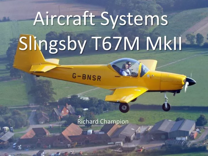
Aircraft Systems Slingsby T67M MkII. Richard Champion. Slingsby T67M MkII Systems. Aim: To learn the important details of the key aircraft systems employed in the Slingsby T67 M MkII aircraft . Objective:

E N D
Aircraft SystemsSlingsby T67M MkII Richard Champion
Slingsby T67M MkII Systems Aim: To learn the important details of the key aircraft systems employed in the Slingsby T67 M MkII aircraft. Objective: By the end of the lesson, you should be able to identify the key elements of the systems and demonstrate knowledge of their correct operation Airmanship: Pilot knowledge. Agenda 1. Fuel System 2. Ignition System 3. Electrical System 4. Oil System 5. Vacuum System 6. Summary 7. Quiz
Description & History • A two seat side by side primary aerobatic military trainer, with IMC capability. • Originally designed by Rene Fournier as theFournier RF-6. • First flight 1974 • All wooden construction, fixed pitch propeller, high aspect ratio wing. • Design sold to Slingsby Aviation in 1981 • Re-designated as T67 • Changed from wooden to composite structure • Developed to M version (for Military) with larger engines and inverted fuel and oil systems • Sold to the UK, US and Canada as primary trainers • Until recently, operated in the UK by Defence Elementary Flying Training School (DEFTS) at Barkston Heath to train Navy and Army pilots. • 260HP version purchased by the USAF (as T3A Firefly), but all scrapped following three fatal crashes.
1. Fuel System • General Description • Fuel contained in two separate wing tanks. • Fuel is fed from one or other of the tanks via a left/right selector valve. • Pumped to engine through a filter, by means of an engine driven pump supplemented by an electrical booster pump. • The engine has a continuous flow fuel injection system incorporating a fuel control unit in place of a carburettor and a fuel pressure sensor. • Vital Statistics • Each tank holds 80.7 litres of which 78.7 litres are usable. • Fuel type is AVGAS 100LL.
Fuel System – Key Points • Inverted systems • Vent pipes are equipped with flapper valves to minimise fuel loss during inverted flight. • Fuel caps incorporate a positive lock and rubber sealing washer. • Fuel is drawn from a collector tank in each of the fuel tanks using a flop tube fitted with a filter and non return valve. • Aerobatics are permitted with full tanks, providing w&b is in limits. • Consumption • Fuel consumption varies with throttle and mixture settings. Operating experience shows an average consumption of 35 lt per hour in normal use.
Fuel System • Instrumentation • Float type content measuring devices supply information to fuel content gauges mounted on the instrument panel. • The gauges are electrical and are protected by the same circuit breaker as the oil temperature, oil pressure and fuel pressure gauges. • A sensor reports fuel pressure at the fuel distributer inlet. Fuel pressure is proportional to fuel flow. • Economy settings are achieved by leaning to the appropriate fuel pressure setting. Fuel Gauges
Fuel System • Control • A fuel selector valve is used to select feed tank. • Settings are OFF, LEFT and RIGHT. • Pilot must monitor and control balance between tanks. • Dual throttles are fitted, enabling HOTAS for left hand pilot. • Opening the throttle increases airflow in the manifold. • The fuel control unit automatically senses airflow and increases fuel pressure to give correct air/fuel mixture for maximum power. • Changes in altitude are compensated for automatically. • The mixture can be weakened for economy cruise using the mixture control.
Fuel Instrumentation and Control Fuel Pressure Manifold Pressure R/H Throttle Mixture Control Fuel selector valve Booster pump switch
2. Ignition System • General Description • Each of the four cylinders is fitted with two sparking plugs. • Two Bendix magnetos are mounted at the back of the engine. • Both magnetos work together, each one supplying one sparking plug in each cylinder. This ensures that the engine will continue to run if one magneto fails. • The left magneto is fitted with an impulse and spark retard device to facilitate engine starting.
Ignition System • Control and Operation • The ignition system is controlled by a key operated switch. • Possible selections are OFF, R, L and BOTH. • In the OFF position, both magnetos are earthed and will not produce a spark. • With R selected, the right hand magneto is live and the left hand magneto is earthed, and vice versa. • Both magnetos are live when BOTH is selected. • The left hand magneto (L) is selected for engine start, switching to BOTH when the engine fires. Prolonged running with one magneto off will lead to plug oiling. • The impulse and spark retard devices fitted to the left hand magneto operate at very low RPM only.
Ignition Control Key operated ignition switch
Ignition System • Potential faults • Magnetos may fail or become permanently live. • These faults may not be apparent during engine operation or shutdown. • A failed magneto may cause rough running and loss of power. Failure of the second magneto would cause the engine to stop. • A permanently live magneto could not be switched off if required. The engine may start if the propeller is turned during maintenance or ground handling. • A series of magneto checks are performed pre and post flight to detect these faults.
Ignition System – Magneto Checks • FUNCTION check • Drop/no stop check performed after start up. Ensures that both magnetos are operating and that each can be switched off if the need arises during flight. • POWER check • Performed immediately before take off at 1800 RPM. • RPM should drop when each magneto is turned off. The drop must be observed, but must not exceed 175 RPM. The difference in RPM between each magneto must not exceed 50 RPM. • SAFETY check • Drop/no stop check performed before engine shutdown. Ensures that both magnetos are earthed when switched off.
3. Electrical System • General Description • A 15 ampere hour rated battery provides a 24 volt DC supply for all systems. • Any equipment requiring AC incorporates its own solid state inverter – No AC distribution system is provided. • A 24v 70 amp alternator charges the battery. The alternator is driven by a friction belt from a pulley on the propeller shaft. • All circuits are protected by circuit breakers accessible to the pilot. • A master switch energises the electrical system.
Electrical System • Alternator Key Points • To protect the alternator it should be switched on just after engine start and off just prior to engine shutdown. • Switching the master switch off when the alternator is on and the engine running will damage the alternator. • A red ALT light flashes when the master is on and the alternator is not giving any output. • A voltage regulator will cut out the alternator in the event of over voltage • An ammeter is fitted to indicate rate of charge or discharge of the battery • Alternator failure will be indicated by the ALT light flashing and the ammeter indicating discharge
Ammeter Alternator warning light Master switch Alternator switch Nothing to do with the alternator!
Electrical System • Circuit Breaker Key Points • Circuit breakers protrude when tripped, showing a white stem. • CBs can be tripped deliberately by the pilot pulling them out, and reset by pushing them in. • If a CB trips, the protected circuit should be switched off (if there is a switch) before resetting. Allow to cool for 30 second before reset. • If CB trips a second time the circuit should be left off and not reset. • Some CBs protect more than one circuit – this is not always indicated on the panel. • CBs must not be held in – this could result in a fire!
Ammeter Circuit Breakers Alternator Circuit Breaker
4. Oil System • General Description • A wet sump oil system lubricates internal bearings under pressure. • Pressurised oil is also provided to the constant speed propeller unit. • Oil is cooled by a thermostatically controlled oil cooler mounted on the left hand side of the engine. • An inverted system is fitted to allow prolonged inverted flight. • Vital Statistics • Oil system capacity – 8 US quarts max, 4 US quarts min. Normal operating limits may be different and any excess will be dumped. • Maximum allowable consumption 0.37 US quarts per hour at 75% power.
Oil System • Inverted System Key Points • System comprises a pump, changeover valve and an oil separator which allows the top of the engine to vent to atmosphere. • During inverted flight, the top of the engine become the sump and vice versa. • On inversion, a steel ball in the separator blocks the vent connection from what is now the bottom of the engine. • The changeover valve directs oil to the pump from the sump or the top of the engine when inverted. • The inverted systems do not work at zero g – e.g. during vertical or knife edge flight. Zero g flight for more than 10 seconds must be avoided. • Oil pressure will drop by 10 to 30 psi immediately following inversion, then rise to 5-10psi less than upright flight within 1 second.
Oil System • Oil System Key Points • Oil pressure should rise to yellow or green segment within 30 seconds. Engine must be shut down immediately if it does not. • There is no minimum temperature for engine run up, but it should not be commenced until engine has been warmed up for 4 minutes from cold. • Engine life is maximised if the oil is warmed to 40⁰C before flight. • Takeoff should only continue if 2,550 RPM is obtainable immediately the throttle is fully opened. • The engine should be warmed during prolonged glides by applying full power for at least 3 seconds every 1,000 ft.
5. Vacuum System • General Description • An engine driven vacuum pump provides suction for the Attitude Indicator. • The vacuum developed by the pump is measured and displayed on the vacuum gauge. • A vacuum of 4.5 to 5.5 Hg is required for reliable operation of the AI. This range is indicated in the green arc on the vacuum gauge. • The only indication of vacuum failure is the gauge. The AI does not have any sort of failure indicator.
Vacuum System Suction Gauge Attitude Indicator
Summary • We have now examined the following key systems: • Fuel • Ignition • Electrical • Oil • Vacuum Questions?
Quiz • What is the maximum time you can fly at zero g? • What is the voltage of the electrical system? • How many minutes must you warm the engine before run up? • How many spark plugs are there? • How many amp hours is the battery rated for? • How much usable fuel is there when the tanks are full? • How many times can a circuit breaker be reset during a flight? • How many pumps have we discussed today? • What is the maximum allowed magneto drop at the power check? • How many vacuum driven instruments are there?