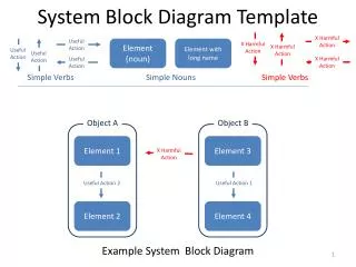
Template based diagram generation
Template based diagram generation. Florian Noyrit December the 2nd 2010. Create a new diagram template. Editor overview. Name of the diagram definition. Prefix used to name the diagram: prefix+name of the owner. Root to start search. The model to apply the template on.

Template based diagram generation
E N D
Presentation Transcript
Template based diagram generation Florian Noyrit December the 2nd 2010
Editor overview Name of the diagram definition Prefix used to name the diagram: prefix+name of the owner Root to start search The model to apply the template on Clear specific information: remove application on a specific model Diagram definitions The kind of diagram to create For which element a diagram should be created and What should be shown in it • Recursively means that the search for elements will be done recursively from the root • Subtypes means that the search for elements will try to mach the type specified AND its subtypes • Stereotyped by is a string consisting of comma separated qualified names of stereotypes (e.g. SysML::Blocks::Block). The search will try to match this stereotype applications Select what should be shown
Case study • Create class diagrams for all packages • Show classes • Show attributes and operations • Show associations • Create an activity diagram for activity1 • Show ControlFlows Laboratory of Model Driven Engineering for Embedded Systems
Create generic templates Create class diagrams for all packages 3-Select the type of the element you want to create diagrams for. Here, select Package 1-Select a diagram kind to create 2-Select “All” Laboratory of Model Driven Engineering for Embedded Systems
Create generic templatesShow classes 3-We want to process all the classes 1-We want to create diagrams for all packages recursively 2-We want to add Classes: these are packagedElements 4-Select Class Laboratory of Model Driven Engineering for Embedded Systems
Create generic templatesShow attributes and operations 1-Select the “All classes” 3-We want to process them all 4-Select Property 2-We want to add Attributes 6-Select Operation 5-We want to add Operations Laboratory of Model Driven Engineering for Embedded Systems
Create generic templates Show associations 3-We want to add them all 1-Select the “All packages” 2-We want to add Associations (which are packagedElements) 4-Select Association Laboratory of Model Driven Engineering for Embedded Systems
Create generic templates Add this diagram definition At this stage, the template is generic Laboratory of Model Driven Engineering for Embedded Systems
Apply template to a specific model 1-Select a UML model to apply this template on 2-Create a new diagram definition Laboratory of Model Driven Engineering for Embedded Systems
Apply template to a specific modelCreate an activity diagram for activity1 3-Select the element you want to create the diagram for. Here, select activity1 1-Select a diagram kind to create 2-Select “Specific” Laboratory of Model Driven Engineering for Embedded Systems
Apply template to a specific modelShow ControlFlows 3-We want to add them all 1-Select the “specific activity1” 2-We want to add ControlFlows (which are edges) 4-Select ControlFlow 5-Add this diagram definition Laboratory of Model Driven Engineering for Embedded Systems
Execute the template An empty Papyrus diagram must be created for the UML model: use the Papyrus wizard Laboratory of Model Driven Engineering for Embedded Systems
Execute the template 2-You get a report of what has been added (green +). If something matches the template definition but failed to be shown on a diagram or a diagram cannot be created, you will get a red X for it 1-When your template is defined : Execute Laboratory of Model Driven Engineering for Embedded Systems
Result Laboratory of Model Driven Engineering for Embedded Systems
Limitations and Future work • If the drag and drop feature is not well implemented then the diagram generation will fail • Post a bug to the developer responsible for the diagram that failed. • Expressivity is clearly not enough • Use queries (Modisco) to define : • for which elements diagrams are to be created • what to show on each diagram • Layout of generated diagrams is not always adequate • Post process generation with advanced auto layout algos • Let the template designer choose which layout to apply on a diagram definition • Report is too laconic • A verbose trace should be generated Laboratory of Model Driven Engineering for Embedded Systems