Advanced Light Source Kicker Design and Performance”
This presentation discusses the requirements, design, and performance of the fast strip-line kicker for the ALS PSB. The goal is to spatially separate a bunch from the main bunch train, allowing for potential single bunch operation throughout the year. The deflection angle, repetition rate, pulse length, and dimensional restrictions are discussed. The calculation of the beam-induced voltages and heat dissipation at the kicker electrodes is also presented.

Advanced Light Source Kicker Design and Performance”
E N D
Presentation Transcript
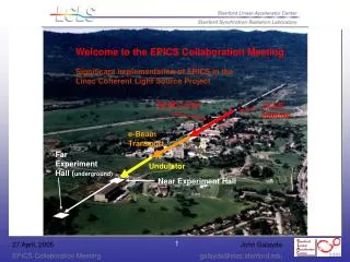
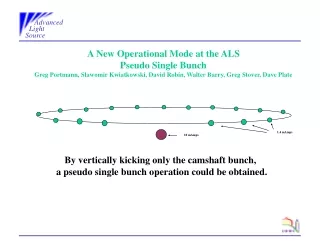
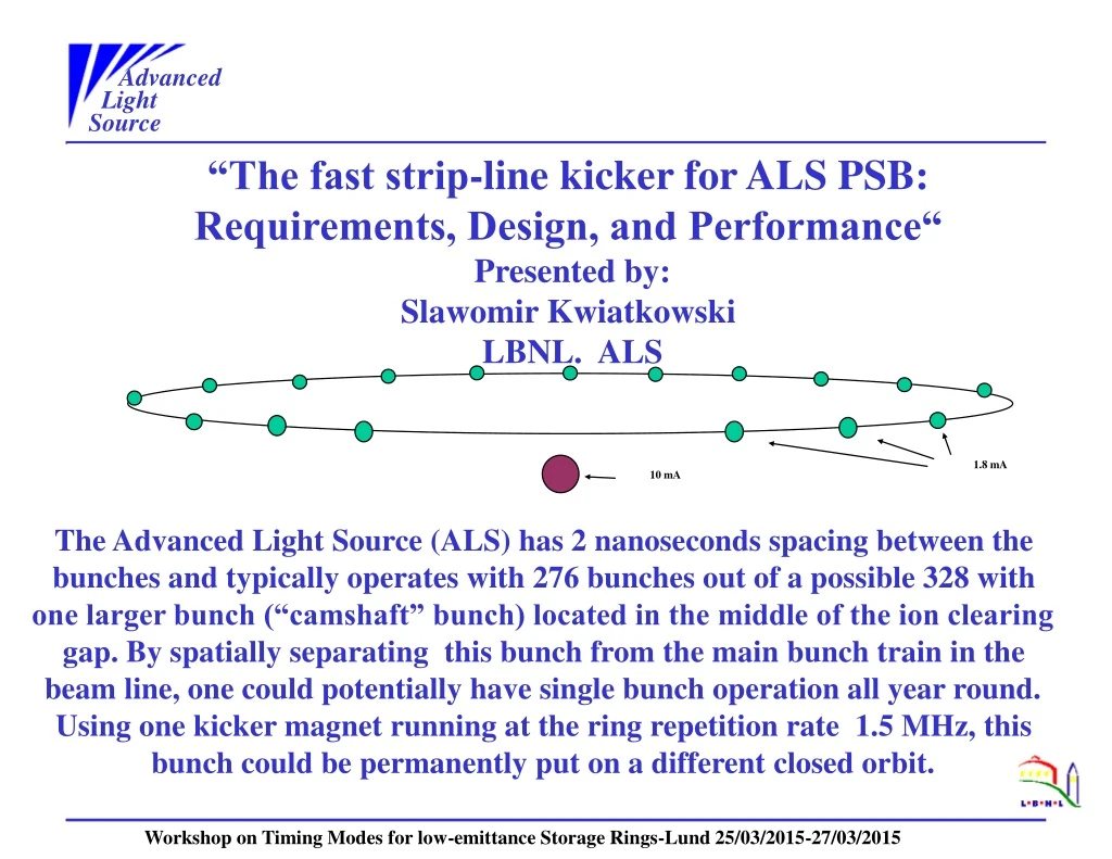
Advanced Light Source 1.8 mA 10 mA “The fast strip-line kicker for ALS PSB: Requirements, Design, and Performance“ Presented by: Slawomir Kwiatkowski LBNL. ALS The Advanced Light Source (ALS) has 2 nanoseconds spacing between the bunches and typically operates with 276 bunches out of a possible 328 with one larger bunch (“camshaft” bunch) located in the middle of the ion clearing gap. By spatially separating this bunch from the main bunch train in the beam line, one could potentially have single bunch operation all year round. Using one kicker magnet running at the ring repetition rate 1.5 MHz, this bunch could be permanently put on a different closed orbit. Workshop on Timing Modes for low-emittance Storage Rings-Lund 25/03/2015-27/03/2015
Advanced Light Source REQUIREMENTS/RESTRICTIONS KICKER PARAMETERS REQUIREMENTS: DEFLECTION ANGLE: >60uRAD REPETATION RATE: 1.5MHz PULSE LENGTH: <100ns DIMENTIONAL RESTRICTIONS: VERTICAL BEAM PIPE APERTURE: >10[mm] HORIZONTAL BEAM PIPE APERTURE: >30[mm] EFFECTIVE KICKER LENGTH: <600[mm]
Advanced Light Source KICKER PULSE AMPLITUDE REQUIREMENTS In the transmission line type kicker two pulse generators operating in push-pull mode generate the plane wave which propagates along the kicker lines. The deflecting force experienced by the beam is the combined effect of the electric and magnetic forces generated by the propagating TEM mode. For the beam traveling in the same direction as the pulse: [1] where: F-transverse deflection force; E-transverse E-field strength; c-speed of light B -induction of the transverse B-field; β-speed factor The relationship between E and H field for the TEM mode in vacuum is described by equation [2] [2] For highly relativistic ALS electron beam equation [ref 1] shows zero deflection for beam and pulse moving in the same direction. For the beam traveling in the opposite direction to the kicker pulse the deflecting forces due to the electric and magnetic fields are equal (for β=1) and they add up. [3]
Advanced Light Source During the passage along the kicker electrodes the beam gains transverse momentum: [4] Taking into consideration that: and The required amplitude of the kicker pulse on each plate equals: [5] where: E-beam energy (in eV); d -distance between kicker plates Θ-deflecting angle; l-kicker length;g -geometry factor for long flat electrodes [3] g=tanh(w/2d); w-strip line width For the required beam deflection angle of 60mrad, beam energy 1.9GeV, effective kicker plates spacing 1.5cm and kicker length 0.6m, the required voltage applied to each electrode should be 712.5 V
Advanced Light Source KICKER DESIGN PROCESS The transverse dimensions of the ALS camshaft kicker were optimized using ANSOFT Designer SV 2-D, a finite element electrostatic code. The resulting geometry is shown in Fig.1. Fig. 2 shows the E-field value along the horizontal median line for the camshaft kicker. The characteristic impedance of the kicker for odd-mode excitation (kicker operation mode) is Zodd =50Ω. For even mode excitation (beam excitation) Zoe =75Ω. The total power dissipated in each electrode is the sum of the power dissipated due to the power flow from the pulse generator to the 50Ω termination resistor and the beam image current flowing along the electrode surfaces. Fig.2 Fig.1
Advanced Light Source CALCULATION OF THE BEAM INDUCED VOLTAGES ON THE CAMSHAFT KICKER ELECTRODES Beam current parameters: Multibunch: Two bunch mode: Average beam current: Iave 500[mA] 35[mA] Bunch length RMS: σt 15[ps] 15[ps] Bunch spacing: τ 2[ns] 333[ns] Bunch charge: q 1nQ 11.5nQ The amplitude of the beam current with bunches having Gaussian distribution is given by [ref.1]: [6]
Advanced Light Source The bottom of each electrode sees the full projection of the beam image current: [7] where:ΔΦ-angle span of the electrode Maximum kicker beam induced voltage: [8] Kicker beam induced voltage: For multibunch mode:VMAX=223V For two bunch mode: VMAX=2570V
Advanced Light Source Heat Dissipation at the Kicker Electrodes The heat dissipated in the each electrode is the sum of the heat generated by the image current of the electron beam and Pulse Generator. It is difficult to calculate the beam generated power in ALS camshaft kicker due to the mismatch between termination load R=50Ω and the strip-line in phase impedance (75 Ω) and fact that each strip-line is terminated with well determined load only at the one end. We did perform the analytical calculations for the case when each strip-line is terminated from both sides with the resistance equal its characteristic impedance. The power dissipated at each electrode by the beam image current could be express in this case [ref 2]: [9] where: Rs- copper resistivity-2.61e-7[Ω] l-electrode length-0.6[m] w-electrode width-0.017[m] Γ(3/4)=1.2254 Pb for 500mA multibunch mode=1.2[W]: Pb for 35mA two bunch=0.97[W]
Advanced Light Source Assuming the sinewave shape of the kicker pulse with T=50ns, peak current IMAX=20A and the pulse repetition rate 1.5MHz, the power dissipated at each electrode by pulse source current could be express by following equation: 2 [10] S- electrode circumference l–electrode length Df-current distribution factor =1.32 (determined using HFSS driven solution)
Advanced Light Source HOM ISSUES We found only one significant longitudinal HOM within our Network Analyzer range (6 GHz). R/Q factor from HFSS calculations 3.5 Figure 4 Figure 3
HOM ISSUES The formula for the longitudinal HOM modes impedance threshold is shown below: Review and Discuss Readiness of HV Disconnect Switch and Filter Cabinet for Installation during ALS May-July 2014 Shut-Down. [11] Where: Nc- Numbers of RF Cavities 1 FHOM-Frequency of particular HOM E0-Beam Energy 1.9[GeV] Qs-synchrotron tune 8.0e-3 I0-average beam current 0.5[A] α-momentum compaction factor 8.5e-4 𝞽𝞮 –longitudinal damping time 4.5e-3[s] For 4.35 GHz at 1.9GeV Zlong_limit=3.7kΩ>ZHOM=1.1kΩ 11
Advanced Light Source Camshaft Kicker Model Figure 5
Advanced Light Source Camshaft Kicker Chamber Figure 6
Advanced Light Source Camshaft Kicker Electrodes Figure 7
Advanced Light Source Kicker Pulse Amplifier Power MOSFET’s have great potential to serve as a high speed high voltage switching devices. The theoretical carrier transit time from the drain to source is on the order of 200ps. The power MOSFET’s are intrinsically capable of switching in about 1ns, but it is not achieved mostly due to the package inductance and gate to source capacitance. The latest model of the pulse amplifier we build is using IXYS DE275X2-102N06A 750W push-pull MOSFET. This transistor has two identical units build at the common isolated substrate (2500V isolation voltage). By connecting two transistor in series, we have build the amplifier capable to deliver 2kV output pulse. The DE275X2-102N06A datasheet is presented at Fig.8.
Advanced Light Source IXYS DE275X2-102N06A Figure 8
Advanced Light Source Positive Pulse Amplifier Figure 9
Advanced Light Source Negative Pulse Amplifier Figure 10
Advanced Light Source Figure 11
Advanced Light Source Pulser performance at 1.5MHz repetition rate Fig. 11 and Fig.12 presents the shortest achievable pulse shapes with the amplitude of 1kVfor negative and positive pulses. Figure 12
Advanced Light Source Figure 13
Advanced Light Source Pulse at 1.4kV d.c. (low repetition rate) Unit saturate at 1.25kV Figure 14
Advanced Light Source Behlke FSWP-51-02 Switch Test Figure 15
Advanced Light Source Behlke FSWP-51-02 Switch Test Figure 16
Advanced Light Source Behlke FSWP-51-02 Switch Test Figure 17
Advanced Light Source REFERENCES: 1.)Beam Instabilities; A Hofmann-Proceedings of CERn Accelerator School-Hotel Paradise, Rhodes, Greece 1993 2). Heating of the Transverse Kicker Electrodes- W. Barry-1/13/94 unpublished material. 3.) Dynamic Devices a Primer on Pickups and Kickers-D.A. Goldberg and G.R. Lambertson –LBL-31664 ESG-160
Advanced Light Source Thank You