Download
1 / 22
220 likes | 235 Vues
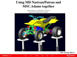
Learn how to create 3D extruded parts in MSC.ADAMS 2005.r2 using b-splines, curves, and points. This tutorial covers topics such as creating extrusions, shading models, filleting, and chamfering.

E N D
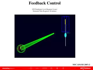
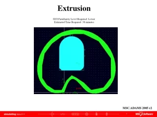
Extrusion GUI Familiarity Level Required: Lower Estimated Time Required: 30 minutes MSC.ADAMS 2005 r2
Topics Covered In this tutorial you will learn how to: • Creating an extrusion from a b-spline • Creating an extrusion using the extrusion tool • Creating an extrusion from a curve • Shading your model • Creating a fillet • Creating a chamfer If you have any difficulties, import the “extrusion_shortcut1. bin” file and proceed from pg 10 If you have any difficulties, import the “extrusion_shortcut2.bin” file and proceed from pg 12 If you have any difficulties, import the “extrusion_shortcut3.bin” file and proceed from pg 17 If you have any difficulties, import the “extrusion_complete.bin” file and proceed from pg 19
Extrusion Problem Create 3-D extruded parts from spline, curves, points.
Create a Marker • Start ADAMS (Units = MMKS, Gravity = No Gravity) • Open the coordinate window and set the working grid spacing to 10mm for both the X and Y • Right-click Rigid Body tool stack, select Marker • Click origin (0,0,0), this is the starting reference for the spline. d c
Create Matrix Elements • Create a matrix element. • Select Build menu Data Elements Matrix New • Select length from Units pull down menu • Select enter input ordered by rows from pull down menu • Enter 12 in Row Count text field • Enter 3 in Column Count text field • Enter values • Click OK 0.0, 0.0, 0.0,-50.0, 0.0, 0.0,-100.0, 50.0, 0.0,-100.0, 150.0, 0.0,0.0, 250.0, 0.0,100.0, 250.0, 0.0,200.0, 150.0, 0.0,200.0, 50.0, 0.0,150.0, 0.0, 0.0,100.0, 0.0, 0.0,50.0, 50.0, 0.0,0.0, 0.0, 0.0 b c d e f a g
Create Curve • Create a curve data element using the data entered into the matrix • Select Build menu Data Elements Curve New • Right click in Matrix Name text field, select ADAMS_MATRIX Guesses MATRIX_1 • Click OK b a c
Create B-Spline • Create b-spline geometry • Select Tools menu Command Navigator • Select geometry create curve bspline • Select CURVE_1 for Ref. Curve Name • Select MARKER_1 for Ref. marker Name • Click OK a c d b e
Extrude B-Spline • Right-click Rigid Body tool stack, select Extrusion • Select Curve from Create profile by: pull down menu • Click GCURVE_1 a c b
Hide Spline • Right-click spline, select BSpline: GCURVE_1 Appearance • Select Off radio button for Visibility • Click OK b a c
Create Extruded Body • Right-click Rigid Body tool stack, select Extrusion • Verify that the Create profile by pull down menu is set to Points and that the Closed checkbox is on • Click on points • Right-click to create c a b
Cut One Solid With Another • Select Cut Out One Solid With Another from Rigid Body tool stack • Click PART_2.EXTRUSION_2 • Right-click on extrusion and select PART_3.EXTRUSION_3 c b a Note: Ignore error warning
Shade Model • Click View menu Render Mode Smooth Shaded a
Create Arc • Click Arc/Circle tool from Rigid Body tool stack • Enter 180.0d in End Angle text field • Click (30, 180, 0) • Click (70, 180, 0) d c a b Note: Ignore error warning
Create Polyline • Click Polyline from Rigid Body tool stack • Click PART_4.ARC_7.V1 • Click (-20, 90, 0) • Right-click to close • Create another polyline from PART_5.POLYLINE_8.V1 to (80, 90, 0) • Create another polyline from PART_6.POLYLINE_9.V2 to (80, 180, 0) b a c e d
Create Chain • Select Chain Construction geometry from Rigid Body tool stack • Click PART_4.ARC_7 PART_5.POLYLINE_8 PART_6.POLYLINE_9 PART_7.POLYLINE_10 • Right-click to close b a Note: Ignore error warning
Create Extrusion of Chain • Click Tools menu Command Navigator • Click geometry create shape extrusion • Select MARKER_4 in Reference Marker text field • Select CHAIN_5 in Profile Curve text field • Enter (5cm) in Length Along Z Axis text field • Click OK a c d e b f
Chamfer • Select Chamfer tool from Rigid Body tool stack • Enter (1.0cm) in Width text field • Click EXTRUSION_15.E29 • Right-click to create b c a
Fillet • Select Fillet tool from Rigid Body tool stack • Enter (2.0cm) in Radius text field • Click EXTRUSION_15.E5 • Right-click to create b c a
Model This is what your screen should look like when your model is complete
Opening/Saving database • To Open • Start Adams • Select Open an existing database radio button • Click OK • Search for saved file • Click Open • To Save: • Click File menu Save Database As • Enter desired name in File Name text field • Click OK d b e c a b c
Topics Covered In this tutorial, you learned how to: • Creating an extrusion from a b-spline • Creating an extrusion using the extrusion tool • Creating an extrusion from a curve • Shading your model • Creating a fillet • Creating a chamfer
Best Practices • Make sure that the working grid is changed • Check entered values for the parts are correct • Check location and orientation of parts/points • Check that the parts are referencing the proper markers