HYDRAULICS
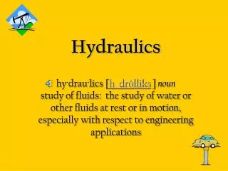
HYDRAULICS. principle.components.structure.application.circuit.h118/1d. Hydraulics. The term “hydraulic” refers to a liquid Hydraulic systems provide a means of remotely controlling a wide range of components by transmitting a force through a confined fluid.

HYDRAULICS
E N D
Presentation Transcript
HYDRAULICS principle.components.structure.application.circuit.h118/1d
Hydraulics • The term “hydraulic” refers to a liquid • Hydraulic systems provide a means of remotely controlling a wide range of components by transmitting a force through a confined fluid. • Oil, water or other incompressible fluids were used as the means harnessing power
Pascal’s Law “Applying pressure anywhere to a body of fluid causes a force to be transmitted equally in all directions, with the force acting at right angles to any surface in contact with the fluid”
Pascal’s Law Pressure = Force / Area “Since each piston has a different surface area, the force exerted on each piston will be different, even though the pressure is the same.” (Application: Hydraulic Lifts)
Hydraulics vs. Pneumatics Pneumatics • Compressible, both in theory and in practical Hydraulics • Not compressible in theory, but in practical compressible up to 0.7%
Advantages of using Hydraulics • Very high force despite small components • Very slow and linear movements • Exact positioning (stops exactly on a point) • Start-up under heavy loads (because there is oil in the actuator though the pump is idling)
Components of Hydraulic System • Hydraulic Power Pack • Hydraulic Actuators • Hydraulic Valves
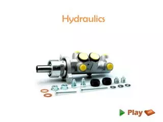
Hydraulic Power Pack Pump: This supplies the oil under pressure that is required to move the system’s cylinder pistons, converting mechanical power to fluid power. Reservoir: Oil storage tank, contains HLP 22 hydraulic oil Accumulator: This is an energy storage device or reservoir for oil pressure. It must be pre-charged so they can store the oil under constant pressure when the system is not moving. Filter: Blocks away all foreign particles Pressure Gauge: For visualization Pressure Line: Connection of power pack with the circuit Return Line: Recycling oil to the tank
Hydraulic Actuators Cylinders: This converts fluid power to linear mechanical power (in rotary fluid power applications, the cylinder would be replaced by a motor). • Single Acting Cylinder, Pushing Load • Double Acting Cylinder, Conventional Type • Double Acting Cylinder, Differential Type
Hydraulic Valves Directional Control Valve A.) 2/2 way valve (more like a shut-off valve) B.) 3/2 way valve (usually for pneumatics) C.) 4/2 way valve (usually to control Double Acting Cylinder) D.) 4/3 way valve (3 types) - 4/3 way valve, Mid position (Center) closed - 4/3 way Mid position closed valve - 4/3 way valve, Pump Bypass (Relief) Center
Hydraulic Valves Check Valve, Spring Loaded: Flow only occurs in one direction. It needs only a certain pressure to start the flow. (Non-return Valve) Pressure Relief Valve: This reduces pressure by returning oil to tank. Valve is closed in normal position. If the opening pressure is reached at the input, the output opens. When the pressure drops below the preset level, the valve closes again.
Hydraulic Valves Flow Control Valve A.) Throttle Valve (Restrictor) B.) One way flow control valve: Used to reduce the speed of cylinder movement C.) Two way flow control valve(Flow Regulator): It maintains the speed of cylinder with increased or decreased load
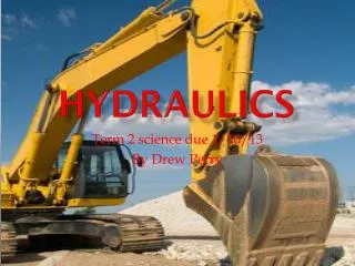
Hydraulic Applications • Mobile Hydraulics - using manual hydraulic in controlling (crane, excavator, back-hoe, lifts, braking systems) • Stationary Hydraulics - using electro-hydraulics in controlling (press machine, molding machine, lathe machine)
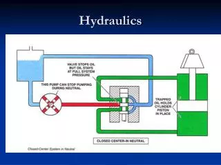
Example Hydraulic Circuits 4/3 way valve, pump bypass Flow control valve/Check Valve